System and method for modular navigated osteotome

a modular and osteotome technology, applied in the field of computer assisted surgery, can solve the problems of revision surgery, increased risks of knee replacement, failure of prosthetic knees, etc., and achieve the effect of more economical

Inactive Publication Date: 2006-11-30
SMITH & NEPHEW INC
View PDF20 Cites 124 Cited by
  • Summary
  • Abstract
  • Description
  • Claims
  • Application Information

AI Technical Summary

Benefits of technology

[0036] The array, the rotation mechanism, the instrument handle, and the cutting device may be modular such that one or more of the components can be discarded or refurbished. For example, the cutting device may be discarded if it becomes dull or bent. The modularity makes the device more economical. It also opens up the opportunity to create additional sizes of the osteotomes and different tip configurations.

Problems solved by technology

Improper positioning and misalignment of the prosthetic knee components and improper ligament balancing commonly cause prosthetic knees to fail, leading to revision surgeries.
This failure increases the risks associated with knee replacement, especially because many patients requiring prosthetic knee components are elderly and highly prone to the medical complications resulting from multiple surgeries.
Also, having to perform revision surgeries greatly increases the medical costs associated with the restoration of the knee function.
Generally, conventional methods are either excessively weighted toward anatomical landmarks on the leg bones or soft tissue balancing (such as adjustment of lengths and tensions of the knee ligaments).
As an additional drawback, varus and valgus knee deformities affect the resection depth determination by anterior and posterior referencing.
Determining the resection depth based on the surrounding soft tissue envelope is also problematic.
If the resection determination is made before the envelope is adequately released, the resection may be inappropriately placed and, likely, excessive.
Generally, ignoring the important anatomical landmarks can result in significant malrotation of the femoral component with respect to the bony anatomy.
By using these anatomical landmarks and ignoring the state of the soft tissue envelope around the knee, the methods encounter certain limitations.
Exposing the condyles to determine the epicondylar axis requires significant tissue resection and increases risks to the patient and healing time.
While easily reproduced, resection of the femur parallel to the posterior femoral condyles is potentially inaccurate because it ignores the dynamic status of the surrounding soft tissue envelope.
This results in excessive rotation of the femoral component upon placement.
The use of posterior referencing to determine femoral component rotation typically results in excessive internal rotation of the femoral component.
However, this method ignores the anatomy of the femur and the extent of the ligament release.
For example, if the knee is severely varus and is inadequately released, then the medial side will remain too tight, which results in excessive external rotation of the femoral component.
The opposite problem arises due to inadequate released knees with valgus-flexion contractures.
The method is not suitable for prediction of the optimal bone cuts based on the combination of the anatomic and the kinematic data and does not employ the combination of such data in prosthetic component positioning and ligament balancing.
Furthermore, the method requires the use of the video camera to acquire the images of the installed trial components and employs complex “machine vision” algorithm to deduce the position of the prosthetic components and other landmarks from the images.
There is an unrealized need for improved systems and methods for computer-assisted soft-tissue balancing, component placement, and surgical resection planning during TKA.
However, problems remain in HTO performance.
A major difficulty with HTO is that the outcome is sometimes not acceptably predictable because it is difficult for a surgeon to attain the desired correction angle.
Current instrumentation cannot accurately produce the desired resection from preoperative plans.
Technical difficulties also arise from the use of fluoroscopy, such as image-intensifier nonlinearities and distortions that compromise accuracy and parallax errors that can provide misleading angular and positional guidance.
However, extensive fluoroscopic time is still needed for the positioning of the jigs.
Inaccurate pin placement can also affect the accuracy of the alignment of the resection, thus increasing shear stresses across the osteotomy.

Method used


Image

  • System and method for modular navigated osteotome
  • System and method for modular navigated osteotome
  • System and method for modular navigated osteotome

Examples


Embodiment Construction

[0082] The following description of the preferred embodiment(s) is merely exemplary in nature and is in no way intended to limit the invention, its application, or uses.

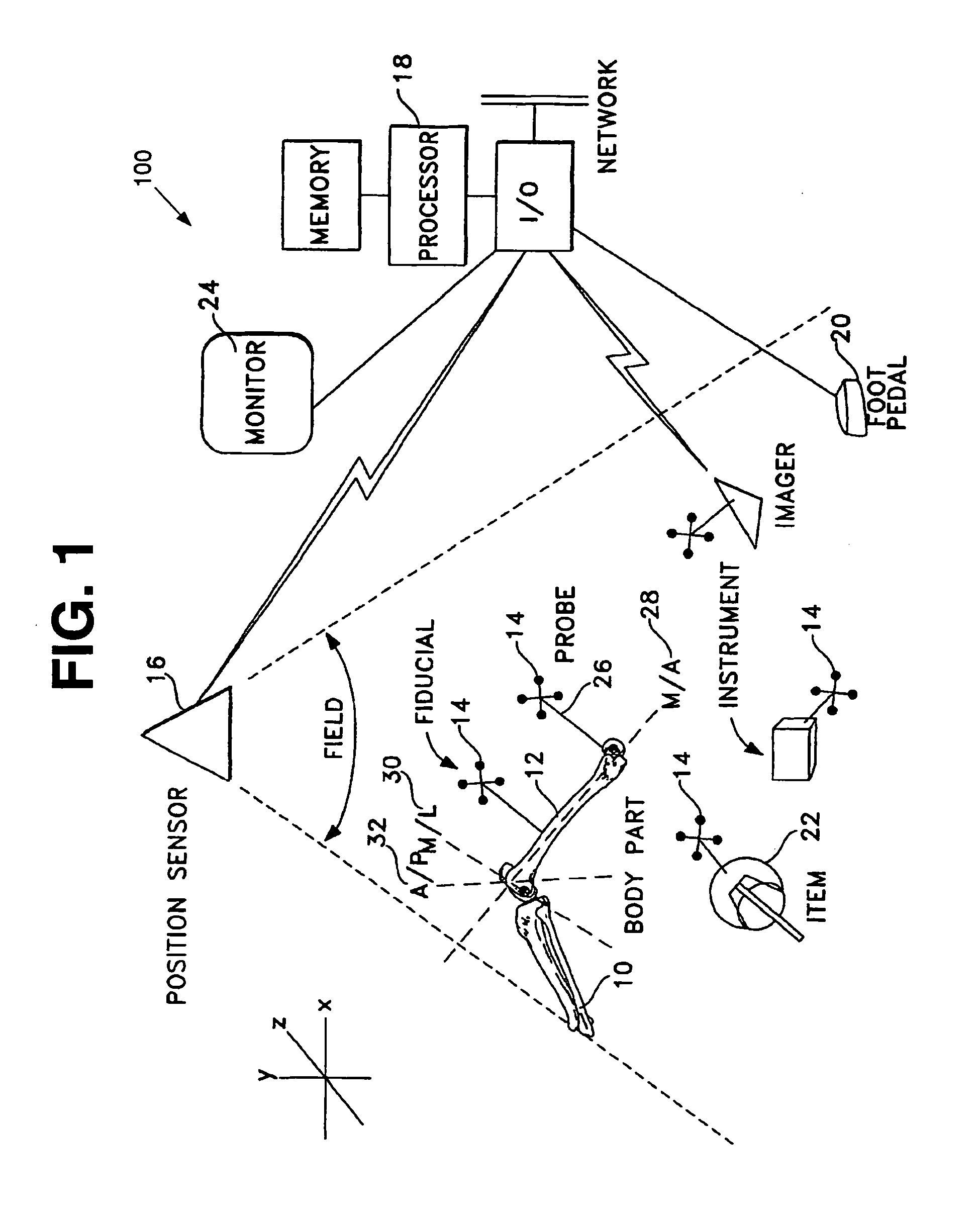
[0083]FIG. 1 is a schematic view showing one embodiment of a computer assisted surgery system 100. The computer assisted surgery system 100 uses computer capacity, including standalone and / or networked, to store data regarding spatial aspects of surgically related items and virtual constructs or references including body parts, implements, instrumentation, trial components, prosthetic components and rotational axes of body parts. Any or all of these may be physically or virtually connected to or incorporate any desired form of mark, structure, component, or other fiducial or reference device or technique which allows position and / or orientation of the item to which it is attached to be sensed and tracked, preferably in three dimensions of translation and three degrees of rotation as well as in time if desired. In so...


PUM


Abstract

An osteotome instrument for use in computer assisted surgery is disclosed. The instrument includes a shaft, a connector, a handle, and a cutter component. The handle has a proximal end portion and a distal end portion. The cutter component is connected to the handle at the distal end portion. The connector is releasably connected to the handle at the proximal end portion, and the connector is adapted to rotate about the shaft relative to the handle. A fiducial for tracking is connected to the connector.

Description

CROSS-REFERENCE TO RELATED APPLICATIONS [0001] This application claims the benefit of U.S. Provisional Application No. 60 / 679,526, filed May 10, 2005, the disclosure of which is incorporated by reference in its entirety.BACKGROUND OF THE INVENTION [0002] 1. Field of the Invention [0003] The present invention relates generally to computer assisted surgery and more particularly to instruments for computer assisted surgery. [0004] 2. Related Art [0005] Computer-assisted surgical systems use various imaging and tracking devices and combine the image information with computer algorithms to track the position of the patient's anatomy, surgical instruments, prosthetic components, virtual surgical constructs, such as body and limb axes, and other surgical structures and components. The computer-assisted surgical systems use this data to make highly individualized recommendations on a number of parameters, including, but not limited to, patient's positioning, the most optimal surgical cuts, ...

Claims


Application Information

Patent Timeline
Patent Type & Authority Applications(United States)
IPC IPC(8): A61B17/00
CPCA61B17/025A61B2019/564A61B17/16A61B17/1675A61B17/1703A61B17/1725A61B19/5244A61B19/54A61B19/56A61B2017/00725A61B2017/0268A61B2019/502A61B2019/505A61B2019/508A61B2019/5255A61B2019/5268A61B2019/562A61B17/154A61B34/20A61B34/25A61B90/39A61B2034/102A61B2034/105A61B2034/108A61B2034/2055A61B2034/2068A61B2034/252A61B2034/254
Inventor TERRILL-GRISONI, LAURALANCULLEY, PATRICK J.
Owner SMITH & NEPHEW INC
Why Eureka
Try Eureka