Implantable vascular graft

a vascular graft and implantable technology, applied in the field of endoluminal vascular prosthesis, can solve the problems of high mortality, large risk, and rupture of the sac, and achieve the effect of reducing migration and risk of endoleaks

Inactive Publication Date: 2006-11-30
SHAOLIAN SAMUEL M +1
View PDF18 Cites 29 Cited by
  • Summary
  • Abstract
  • Description
  • Claims
  • Application Information

AI Technical Summary

Benefits of technology

[0012] There is provided in accordance with one aspect of the present invention, an endoluminal prosthesis having an endoskeleton for supporting tubular polymeric sleeve, and a partial exoskeleton for positioning at the anatomically proximal end, to minimize migration and risks of endoleaks. The prosthesis comprises at least one elongate flexible wire, formed into a plurality of axially adjacent tubular segments spaced along an axis. Each tubular segment comprises a zig-zag section of wire, having a plurality of proximal bends and distal bends. At least one of the plurality of proximal bends and plurality of distal bends have loops thereon. A tubular polymeric sleeve is carried by the prosthesis.
[0020] In accordance with a further aspect of the present invention, there is provided a flexible self expandable graft. The graft comprises a tubular main body support structure, having a proximal end and a distal end. The tubular body comprises at least a first tubular segment attached to a second tubular segment. A tubular polymeric sleeve surrounds at least a portion of the graft. Each of the first and second tubular segments comprise a plurality of proximal bends and distal bends connected by struts, surrounding a longitudinal axis such that a first strut is on a first side of the axis and a second strut is on a second side of the axis opposing the first side. In at least one segment, the first strut is shorter than the second strut. In some applications, at least two or three or four or more adjacent segments are provided with a shorter strut or struts on a first side of the axis compared to the corresponding strut or struts on the second side of the axis, to facilitate curvature of the graft.

Problems solved by technology

When left untreated, the aneurysm may eventually cause rupture of the sac with ensuing fatal hemorrhaging in a very short time.
High mortality associated with the rupture led initially to transabdominal surgical repair of abdominal aortic aneurysms.
Surgery involving the abdominal wall, however, is a major undertaking with associated high risks.
There is considerable mortality and morbidity associated with this magnitude of surgical intervention, which in essence involves replacing the diseased and aneurysmal segment of blood vessel with a prosthetic device which typically is a synthetic tube, or graft, usually fabricated of Polyester, Urethane, DACRON@, TEFLON@, or other suitable material.
Thus, if the patient is not receiving routine examinations, it is possible that the aneurysm will progress to the rupture stage, wherein the mortality rates are significantly higher.
Disadvantages associated with the conventional, prior art surgery, in addition to the high mortality rate include the extended recovery period associated with such surgery; difficulties in suturing the graft, or tube, to the aorta; the loss of the existing aorta wall and thrombosis to support and reinforce the graft; the unsuitability of the surgery for many patients having abdominal aortic aneurysms; and the problems associated with performing the surgery on an emergency basis after the aneurysm has ruptured.
The graft must be secured, or sutured, to the remaining portion of the aorta, which may be difficult to perform because of the thrombosis present on the remaining portion of the aorta.
Moreover, the remaining portion of the aorta wall is frequently friable, or easily crumbled.
Since many patients having abdominal aortic aneurysms have other chronic illnesses, such as heart, lung liver, and / or kidney disease, coupled with the fact that many of these patients are older, the average age being approximately 67 years old, these patients are not ideal candidates for such major surgery.

Method used


Image

  • Implantable vascular graft
  • Implantable vascular graft
  • Implantable vascular graft

Examples


Embodiment Construction

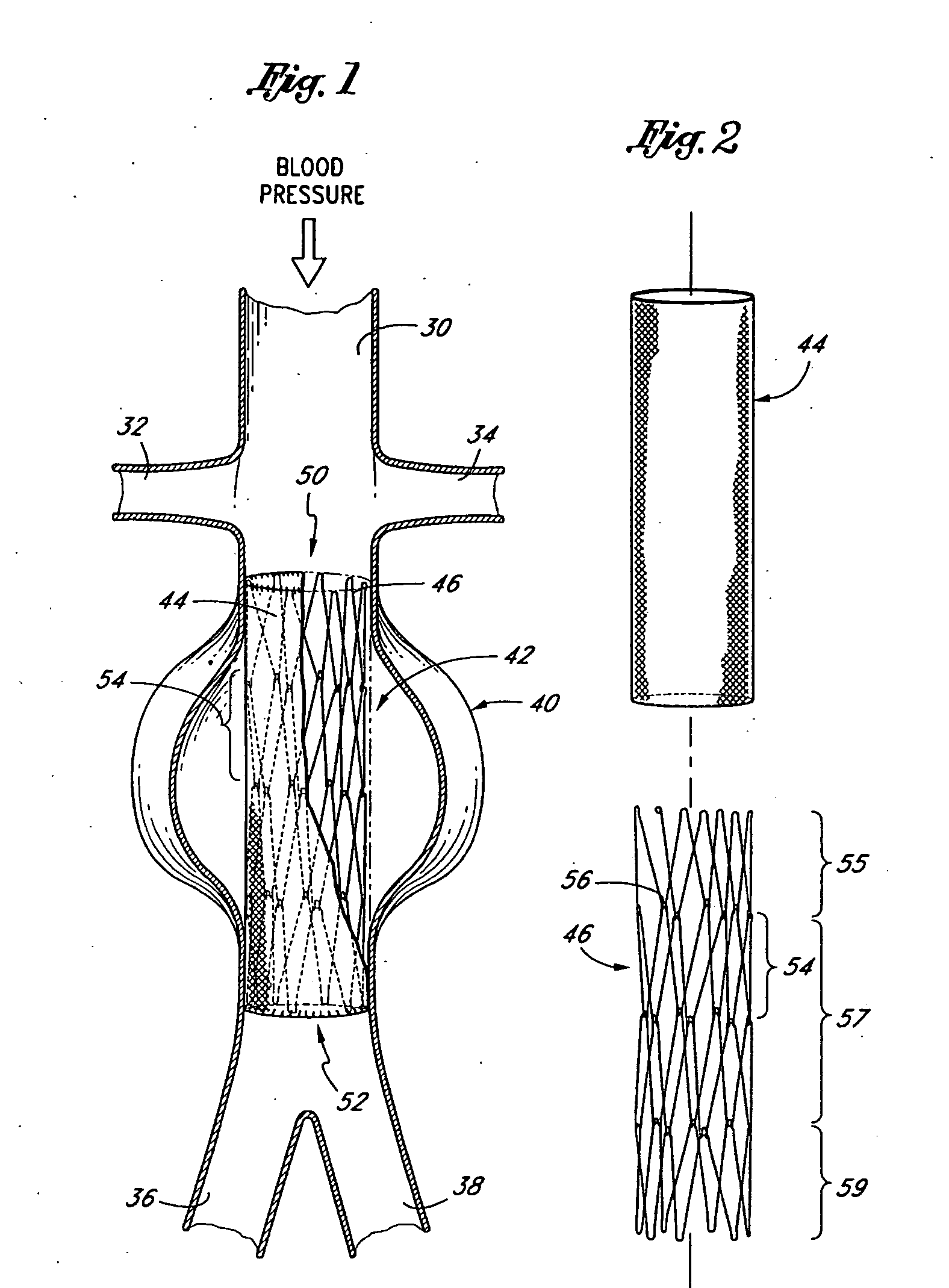
[0073] Referring to FIG. 1, there is disclosed a schematic representation of the abdominal part of the aorta and its principal branches. In particular, the abdominal aorta 30 is characterized by a right renal artery 32 and left renal artery 34. The large terminal branches of the aorta are the right and left common iliac arteries 36 and 38. Additional vessels (e.g., second lumbar, testicular, inferior mesenteric, middle sacral) have been omitted for simplification. A generally symmetrical aneurysm 40 is illustrated in the infrarenal portion of the diseased aorta. An expanded straight segment endoluminal vascular prosthesis 42, in accordance with the present invention, is illustrated spanning the aneurysm 40.

[0074] The endoluminal vascular prosthesis 42 includes a polymeric sleeve 44 and a tubular wire support 46, which are illustrated in situ in FIG. 1. The sleeve 44 and wire support 46 are more readily visualized in the exploded view shown in FIG. 2. The endoluminal prosthesis 42 i...


PUM


Abstract

Disclosed is a tubular endoluminal vascular prosthesis, useful in treating, for example, an abdominal aortic aneurysm. The prosthesis comprises a self-expandable wire support structure having a tubular main body support and first and second branch supports. The support structure may include sliding links to permit flexibility while maintaining patency of the central lumen. The branch supports may articulate with the main body to permit the branches to pivot laterally from the axis of the main body throughout a substantial range of motion. Exoskeleton components or barbs may be provided to resist migration and endoleaks.

Description

[0001] This is a continuation-in-part of U.S. patent application Ser. No. 09 / 728,582, filed Dec. 1, 2000, which is a continuation-in-part of U.S. patent application Ser. No. 09 / 251,363, filed Feb. 17, 1999, entitled “Articulated Bifurcation Graft”, now U.S. Pat. No. 6,197,049 which is a continuation-in-part of U.S. patent application Ser. No. 09 / 210,280, filed Dec. 11, 1998, entitled “Endoluminal Vascular Prosthesis”, now U.S. Pat. No. 6,187,036.BACKGROUND OF THE INVENTION [0002] The present invention relates to an endoluminal vascular prosthesis, and in particular, to a self-expanding bifurcated prosthesis for use in the treatment of abdominal aortic aneurysms. [0003] An abdominal aortic aneurysm is a sac caused by an abnormal dilation of the wall of the aorta, a major artery of the body, as it passes through the abdomen. The abdomen is that portion of the body which lies between the thorax and the pelvis. It contains a cavity, known as the abdominal cavity, separated by the diaphr...

Claims


Application Information

Patent Timeline
Patent Type & Authority Applications(United States)
IPC IPC(8): A61F2/90A61B17/00A61F2/00A61F2/06A61F2/82
CPCA61F2/07A61F2220/0075A61F2/90A61F2/954A61F2/958A61F2/966A61F2002/065A61F2002/067A61F2002/075A61F2002/828A61F2250/0039A61F2/89A61F2002/072A61F2230/0054A61F2220/005A61F2220/0058A61F2/856A61F2/9661
Inventor SHAOLIAN, SAMUEL M.ZENG, FRANK M.
Owner SHAOLIAN SAMUEL M
Why Eureka
Try Eureka