
Method for computing a target setting value

a target setting and target value technology, applied in the field of target setting value computing, can solve the problems of not being able to adapt the harvesting machine and/or its working unit to the current harvesting process, still relatively difficult for operators to adjust the machine, and inexperienced and/or untrained operators, etc., to achieve reliable, simple and automatic selection of target setting value, and optimize the control of the working unit

Inactive Publication Date: 2006-11-30
CLAAS SELBSTFAHRENDE ERNTEMASCHINEN GMBH
View PDF9 Cites 27 Cited by
  • Summary
  • Abstract
  • Description
  • Claims
  • Application Information

AI Technical Summary

Benefits of technology

[0006] It is therefore an object of the present invention to create an improved target setting value determination method, and a method and control unit for controlling a working unit of a harvesting machine that permit the most reliable, simple and automatable selection of a target setting value, even when very complex setting dependencies are involved, the target setting value being optimally adapted to the particular harvesting process, and to therefore permit optimized control of the working unit.
[0011] Combining the operating-result curves ensures that, even when the various operating-result parameters have very complex dependencies on the particular control parameters, an optimum target setting value is still found for the current harvesting conditions, thereby ensuring that the machine achieves an operating result that is optimum overall for the given conditions.
[0017] The measured values can be preferably acquired by measuring the particular control parameter alternately at high and low setting values. In this manner, the situation can be prevented in which, during extended operation in a certain working range of the control parameter, systematic measurement errors are prevented from forming and being added accumulatively. This also prevents the possibility of the working units becoming overloaded when, e.g., operating-result measured values must be acquired in an extreme working range of the control parameter.
[0018] The number and scattering of measured values, i.e., the working range across which the setting values of the control parameter for recording the measured values vary, depends on the circumstances of the particular measurement, the type of control parameter, the type of operating-result parameter, and, possibly, on the mathematical function to be adapted, including, in particular, any advance knowledge of the curve to be expected. A fixed number of setting values can be specified in advance, for example. It can also be specified in advance that exactly certain setting values of the control parameter must be applied to acquire the operating-result measured values. It is also possible to select the number and position of the setting values as a function of current conditions and / or on the basis of advance knowledge of previous optimization cycles, etc., especially for use in the current computation of the target setting value. It must be taken into account that a large variance, i.e., the broadest possible range of variation of the control parameter, has the advantage that it increases the level of certainty with which a mathematical function that describes the actual curve as exactly as possible can be graphed. On the other hand, performing a measurement within a small range of variation has the advantage that measuring time is shortened and it is not necessary to work in extreme loss ranges while the measurement is being performed, provided, e.g., that losses must be measured as operating results. As a result of the method according to the present invention for computing the setting value, the losses that occur during the optimization process itself are less substantial.

Problems solved by technology

Despite the many setting aids offered to operators by the manufacturers of harvesting machines—such as comprehensive operator training, printed lists of setting values predetermined for various harvesting situations that the operator can refer to, and electronic tools such as electronic fieldwork information systems preprogrammed with optimized combinations of setting values for highly diverse harvesting situations for the operator to choose from—it is still relatively difficult for operators to adjust the machine such that it functions in an optimum manner in accordance with the desired requirements.
This is the case, in particular, for inexperienced and / or untrained operators, particularly at the beginning of a harvesting season.
In many cases, therefore, the harvesting machine and / or its working units are not adapted to the current harvesting process in an optimum manner.
As a result, the available harvesting capacity of the machine is under-utilized, poor operating results are obtained, or, in some cases, unnecessary crop losses result.
Since a system is involved with most of the working units on harvesting machines, however, setting one control parameter affects highly diverse operating-result parameters.
The losses due to cleaning are the portions of grain carried out of the machine with the non-grain components as a loss.
Unfortunately, it is not necessarily the case that, when the blower speed is varied from a certain point outward in a certain direction, that all of the various operating-result parameters mentioned above, e.g., losses due to cleaning, total tailings and grain tailings, are automatically improved, since the minimum values of the various operating-result parameters are not all located at the same blower speed.

Method used


Image

  • Method for computing a target setting value
  • Method for computing a target setting value
  • Method for computing a target setting value

Examples


Embodiment Construction

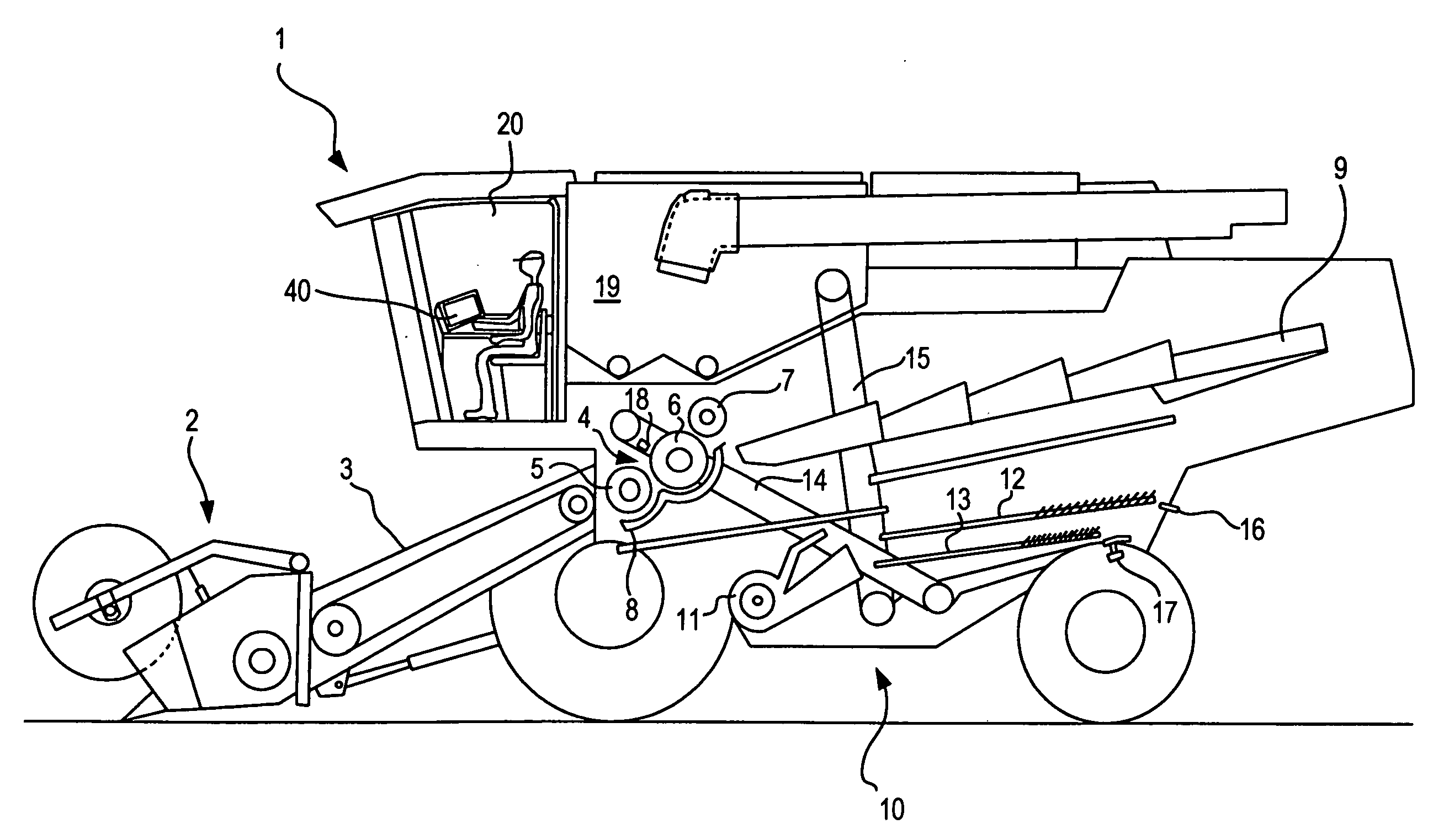
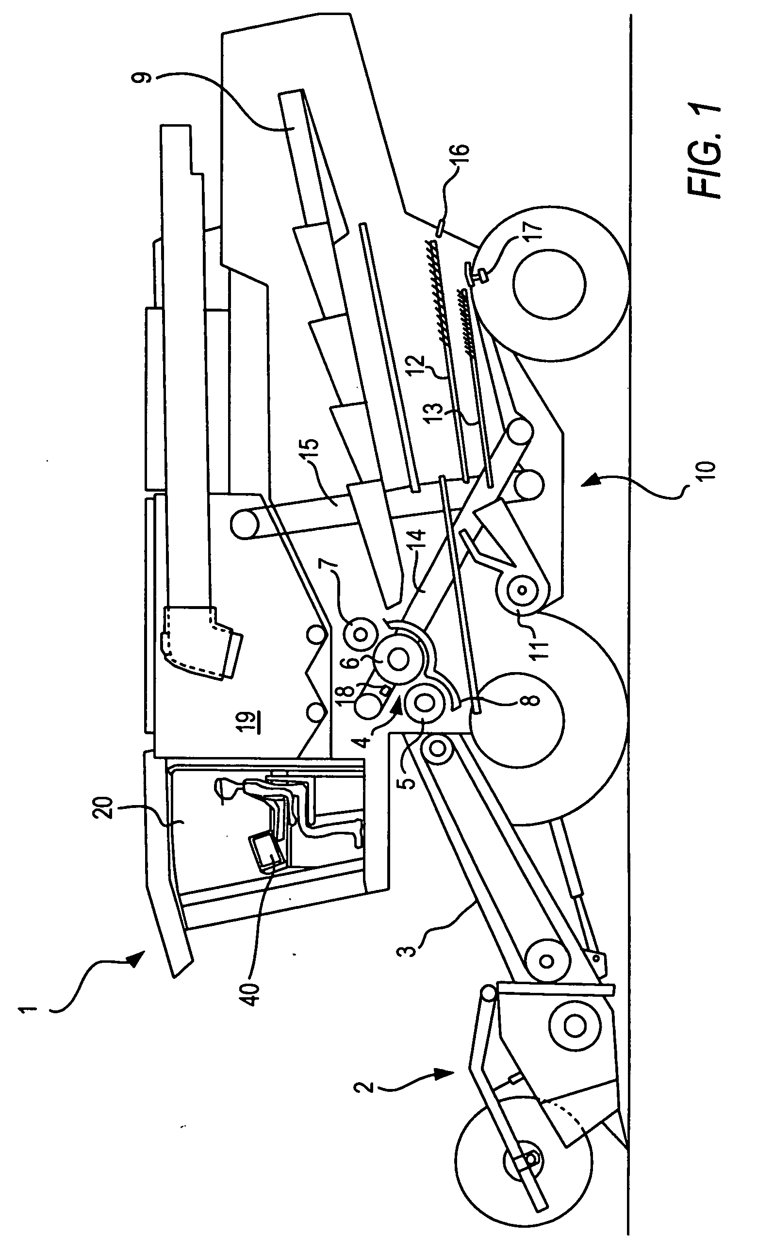
[0054] The exemplary embodiment of the present invention shown in FIG. 1 is a self-propelled combine harvester 1 with a tangential or cross-flow threshing mechanism 4 and a plurality of shakers 9 located behind it, as the separating unit. The separating unit is composed of a plurality of tray-type shakers 9 with a plurality of shaking speeds. A cleaning unit 10 is located beneath shaker 9, which is composed of a plurality of sieves 13 located one on top of the other, and a blower 11.

[0055] The mode of operation of a combine harvester 1 of this type is as follows:

[0056] Using a reel of the cutting disc, the crop material is placed on mowing unit 2 and is cut using knives. The crop material is then conveyed via a header auger and a feed rake in a feeder housing 3 to the inlet of threshing mechanism 4.

[0057] A feed and / or pre-acceleration cylinder 5 is located at the inlet of threshing mechanism 4. Located behind threshing mechanism 4, in the direction of crop flow, is a cylinder 6 ...


PUM


Abstract

In a method for computing a target setting value—which is adapted to a harvesting process—for a control parameter of a working unit of a harvesting machine, operating-result curves are plotted for a plurality of different operating-result parameters as a function of the related control parameter, a target setting value of the control parameter is subsequently computed based on a combination of the plotted operating-result curves, and a method and a corresponding control unit for controlling a working unit of a harvesting machine, and a harvesting machine with a control unit of this type are also provided.

Description

BACKGROUND OF THE INVENTION [0001] The present invention relates to a method for computing a target setting value—which is adapted to a harvesting process—for a control parameter of a working unit of a harvesting machine, in particular a combine harvester. The present invention further relates to a method and a corresponding control unit for controlling a working unit of a harvesting machine, and a harvesting machine with a control unit of this type. [0002] Modern agricultural harvesting machines, in particular self-propelled harvesting machines such as combine harvesters, forage harvesters, etc., include one or more adjustable working units for processing various types of crops. With modern harvesting machines, the individual units are equipped with adjusting devices—which are usually remotely controllable from the driver's cab—with which various control parameters of the working units can be set. Typical working units of a combine harvester are, e.g., the threshing mechanism, whic...

Claims


Application Information

Patent Timeline
IPC IPC(8): G05D11/00
CPCA01D41/127
Inventor BEHNKE, WILLIBAUMGARTEN, JOACHIMNEU, SEBASTIAN
Owner CLAAS SELBSTFAHRENDE ERNTEMASCHINEN GMBH
Learn More