

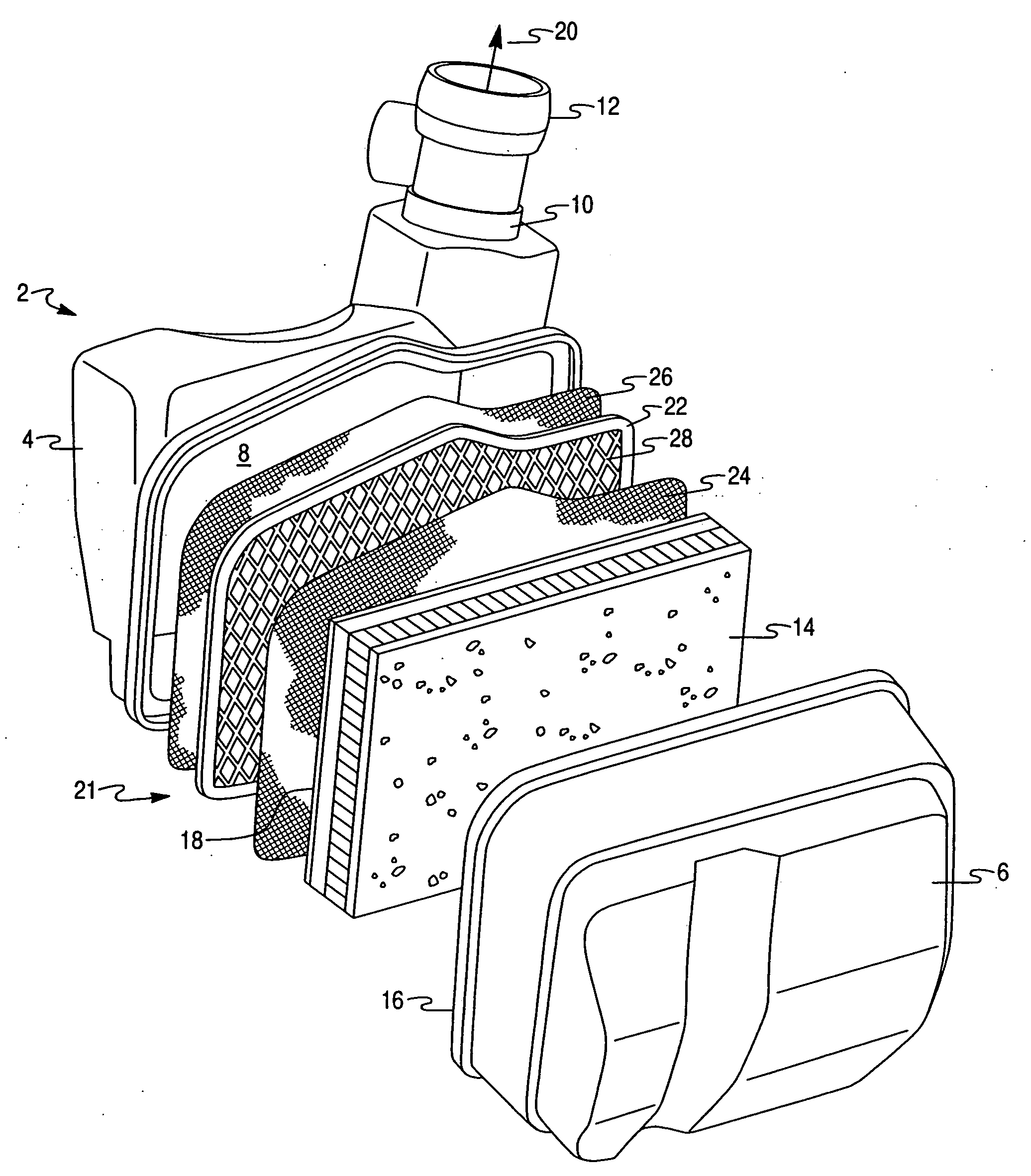
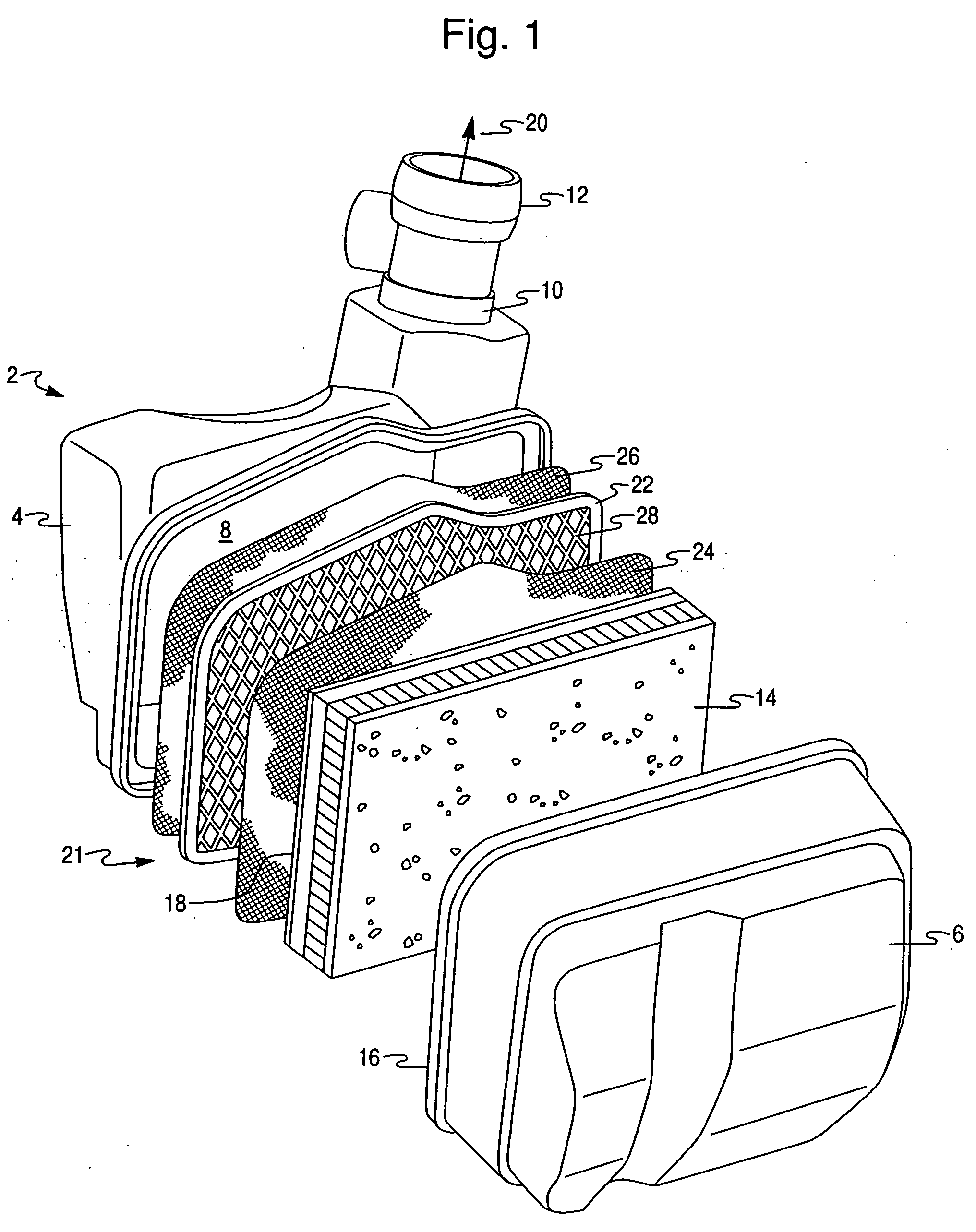
Coated screen adsorption unit for controlling evaporative hydrocarbon emissions
a technology of evaporative hydrocarbons and adsorption units, which is applied in the direction of chemistry apparatus and processes, separation processes, dispersed particle separation, etc., can solve the problem that prior art systems and methods devote relatively little attention to prevention
- Summary
- Abstract
- Description
- Claims
- Application Information
AI Technical Summary
Benefits of technology
Problems solved by technology
Method used
Image

Examples
example 1
[0071] Sulfuric acid-leached (“SAL”) beta zeolite was prepared in accordance with the procedure set forth in Example 5 of U.S. Pat. No. 6,171,556. The SAL beta zeolite was then steamed in an atmosphere of air with 60% of steam at 650° C. for 24 hours to give a final product having a SiO2 / Al2O3 ratio of about 200.
[0072] 500 g of the steamed-SAL final product were dispersed in 521 g of deionized water to form a slurry having a 48% solid content. The slurry was then ball milled such that 90% of the particles had a particle size of less than 9.5 microns. A final slurry was achieved by adding the slurry with 21 g of a colloidal polyacrylic dispersant and 154 g of a polyacrylic latex binder having a solids content of about 50 wt %, a pH of about 6 and a maximum viscosity of 400 cps.
example 2
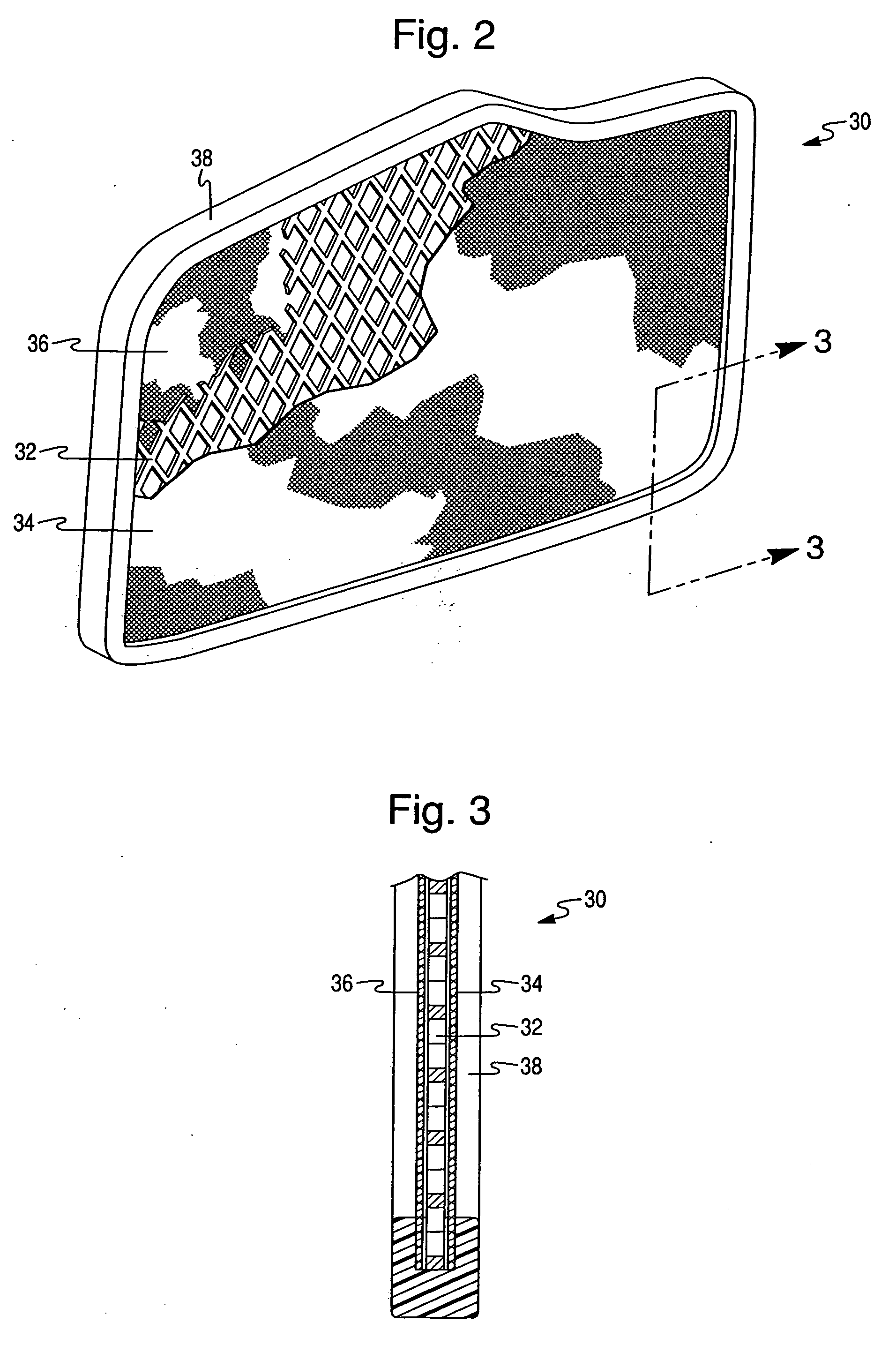
[0073] A wire screen mesh comprising a Cr—Al—Fe alloy containing a wire diameter of 0.028 inches and 12 by 12 wires per linear inch is coated with the final slurry obtained from Example 1. The coated screen is dried and placed in a programmable oven and the temperature was slowly raised to 105° C. and maintained at such temperature for 1 hour. The washcoat dry gain is 6.4 g. The screen is again coated by the same procedure resulting in a coating having a final dry gain of 12.1 g.
example 3
[0074] A slurry of sulfuric acid leached beta zeolite was prepared as in Example 1, with polyacrylic latex binder, organic thickener, solids content of about 50%, and pH of about 6. The slurry was spray coated onto an aluminum wire screen having a mesh size of 12×12 wires per inch with 0.023″ diameter wires. Approximately 22 g of coating were applied to a screen of 12″×8¼″ face area. Prior to coating the aluminum screen, it was pre-coated with silica sol solution and dried at 70° C. The coated screen was assembled in a frame of nylon between two layers of nylon mesh having an opening of 300 micron.
[0075] The assembly was installed into the air cleaner of a vehicle between the air filter and the engine. Standard hot-soak followed by 48 hour diurnal SHED (Sealed Housing for Evaporative Determination) tests were conducted of this air intake containing the zeolite coated screen assembly and compared to SHED tests conducted with the stock air intake system having no hydrocarbon adsorber...
PUM
| Property | Measurement | Unit |
|---|---|---|
| Diameter | aaaaa | aaaaa |
| Diameter | aaaaa | aaaaa |
| Adsorption entropy | aaaaa | aaaaa |
Abstract
Description
Claims
Application Information