Multi-location fuel injection system

Active Publication Date: 2006-12-07
ARCTIC CAT
View PDF21 Cites 18 Cited by
  • Summary
  • Abstract
  • Description
  • Claims
  • Application Information

AI Technical Summary

Benefits of technology

[0013] Thus, the two-stroke engine of the present invention provides the advantages of various type

Problems solved by technology

However, such engines typically emit greater amounts of pollutants, such as hydrocarbons and carbon monoxide.
Such a system may decrease emissions, but may have the effect of decreasing the peak horsepower produced at wide open throttle (WOT).
Some of the lo

Method used


Image

  • Multi-location fuel injection system
  • Multi-location fuel injection system
  • Multi-location fuel injection system

Examples


Example

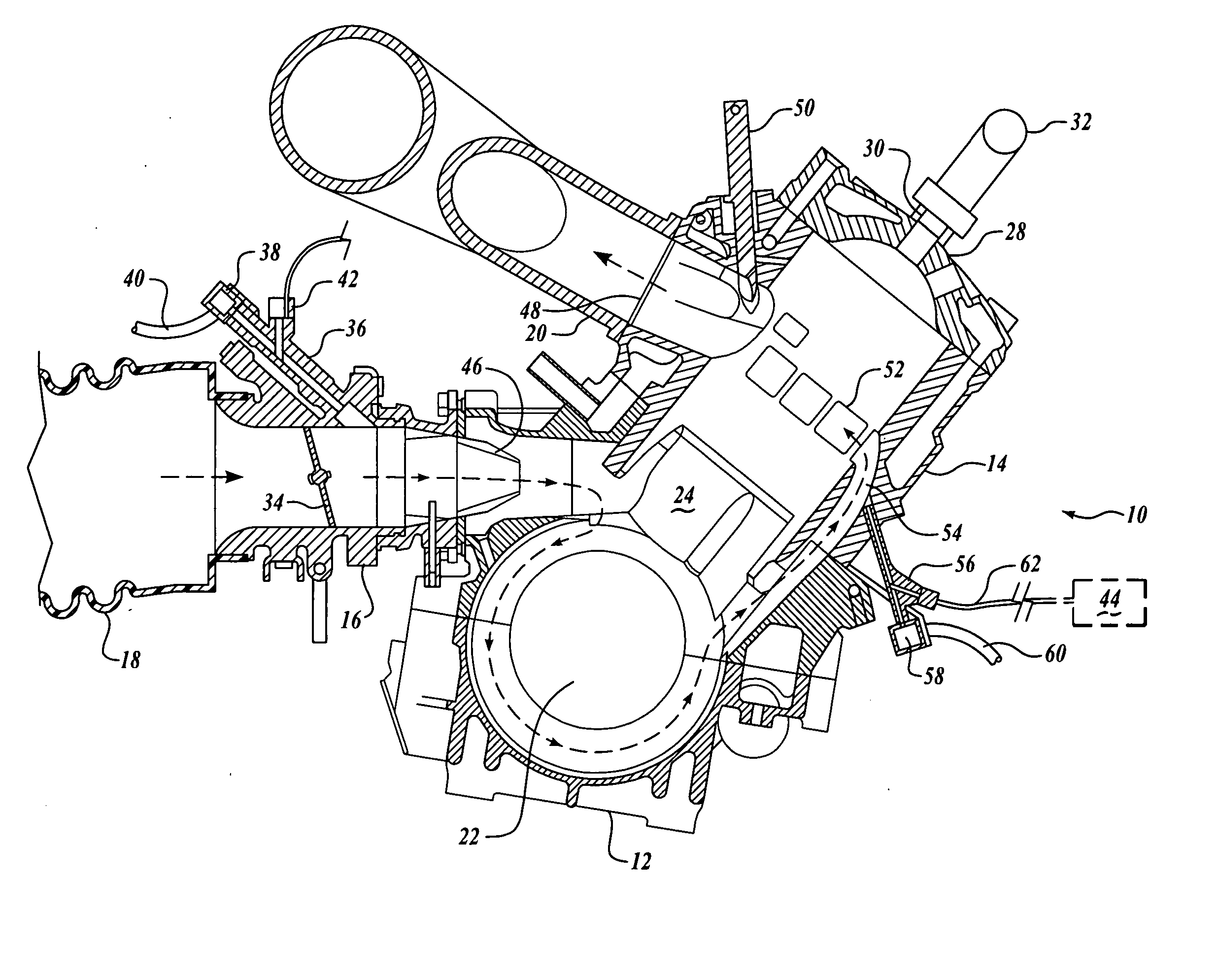
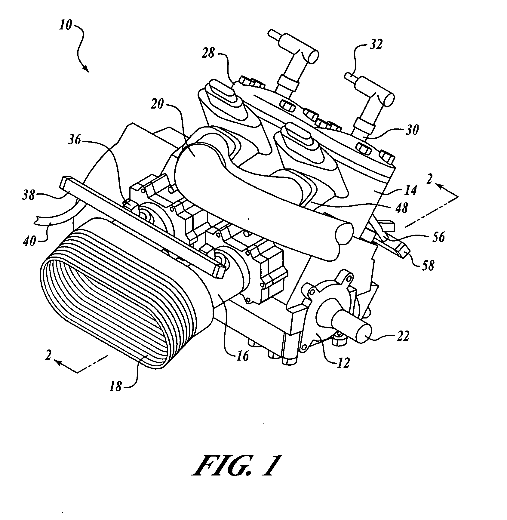
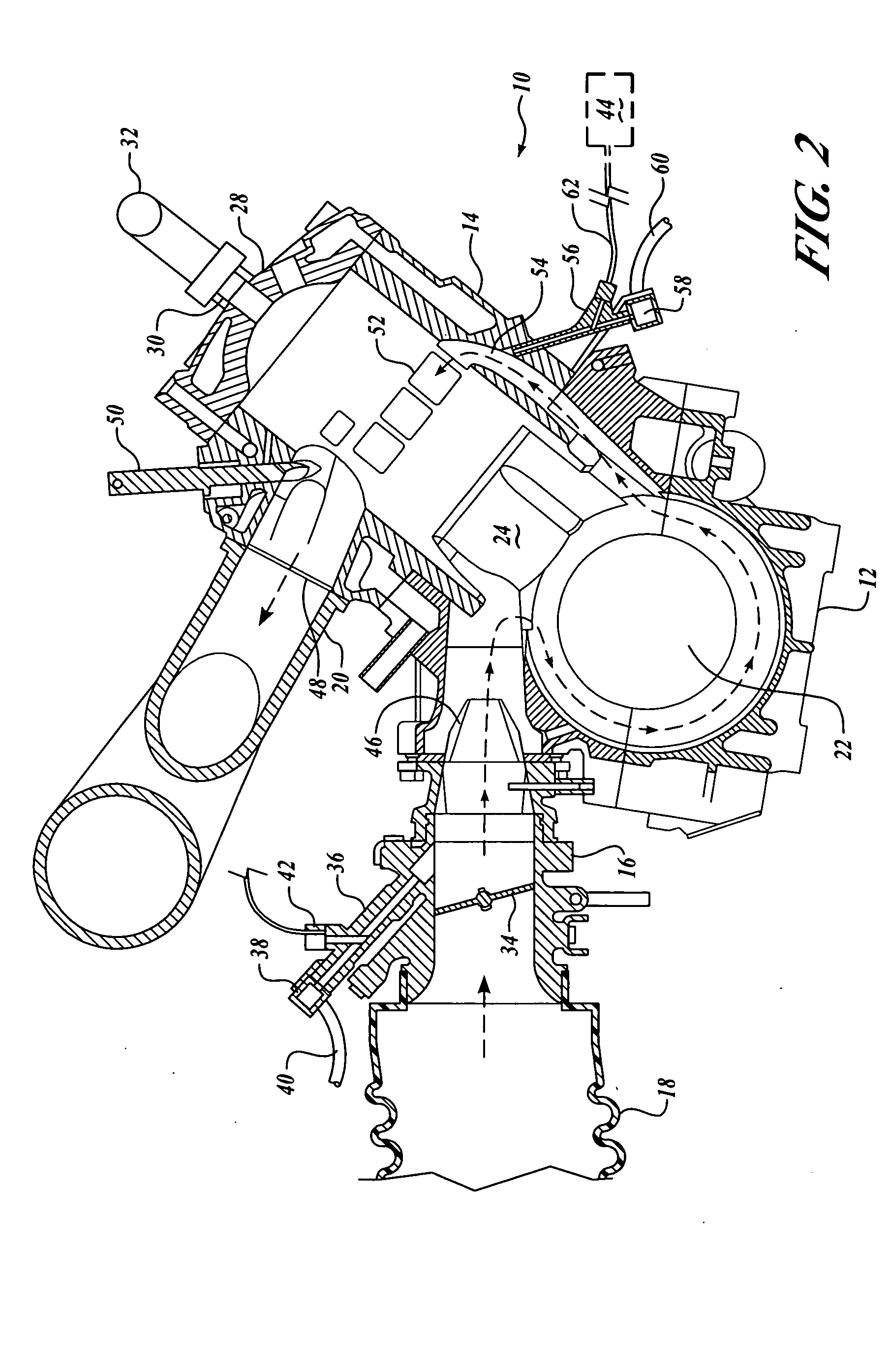
[0019] The figures illustrate external and cross-sectional views of a two-stroke internal combustion engine 10 utilizing the fuel delivery system of the present invention. Engine 10 is, for the most part, of a conventional design as might be utilized, for example, in a snowmobile. Engine 10 includes a crank case 12, right and left cylinders 14, right and left throttle bodies 16, an air boot 18, and an exhaust manifold 20. In actual use, engine 10 will be bolted into the chassis of the snowmobile or secured to the device with which it is to be used. Crank case 12 carries a crank shaft 22 to which is connected the drive elements of the vehicle.

[0020] Throughout this description, individual elements such as a piston or cylinder maybe described. This would be understood that multiple cylinders, pistons, throttle bodies, and so on may be utilized. In the preferred embodiment, a dual cylinder arrangement is employed with two cylinders, pistons, throttle bodies, and associated componentry...


PUM


Abstract

A two-stroke engine having both a direct injector and an indirect injector. The direct injector injects fuel into the cylinder without passing through the crank case. The indirect injector is in fluid communication with the crank case. It provides fuel delivery through the crank case and through a transfer channel to the cylinder. A controller is coupled to the direct injector and to the indirect injector. The controller starts, stops, and varies the fuel delivery of each injector. The controller is programmed to increase the fuel delivery of the indirect injector at a predetermined engine speed. The controller maintains primary fuel flow through the direct injector below a predetermined engine speed. The controller varies the fuel delivery based on at least one of following: engine speed, throttle position, exhaust valve position, intake air temperature, exhaust temperature, barometric pressure, coolant water temperature, and piston position.

Description

FIELD OF THE INVENTION [0001] This invention relates generally to fuel injection systems for internal combustion engines and, more specifically, to multipoint fuel injection in two-stroke engines. BACKGROUND OF THE INVENTION [0002] Two-stroke engines are widely used in various applications, such as for snowmobiles. The high power-to-weight ratios that these engines provide make them desirable. However, such engines typically emit greater amounts of pollutants, such as hydrocarbons and carbon monoxide. Efforts to reduce harmful emissions have included the use of various fuel injection systems. A standard fuel injection process employs a throttle body with a fuel and oil injection into the air flow. The flow then proceeds to the crankcase and into the cylinder under action from the piston. This may be somewhat cleaner burning than a carbureted system with a better control of the fuel delivery. [0003] A semi-direct fuel injection process has also been developed involving injection of t...

Claims


Application Information

Patent Timeline
IPC IPC(8): F02B33/04F02B25/00F02D13/02
CPCF02B17/005F02B25/14F02M69/046F02B33/04F02B2075/025F02B25/20
Inventor JOHNSON, DANIEL J.
Owner ARCTIC CAT
Why Eureka
Try Eureka