Method for estimating the rotor time constant of an induction machine

Active Publication Date: 2006-12-07
OY ABB
View PDF10 Cites 21 Cited by
  • Summary
  • Abstract
  • Description
  • Claims
  • Application Information

AI Technical Summary

Benefits of technology

[0005] It is an object of the present invention to provide an alternative method that avo

Problems solved by technology

The estimation of rotor time constant requires an accurate estimate of stray inductance, which makes the estimation in U.S. Pat. No. 5,929,400 prone to errors.
The

Method used


Image

  • Method for estimating the rotor time constant of an induction machine
  • Method for estimating the rotor time constant of an induction machine
  • Method for estimating the rotor time constant of an induction machine

Examples


Example

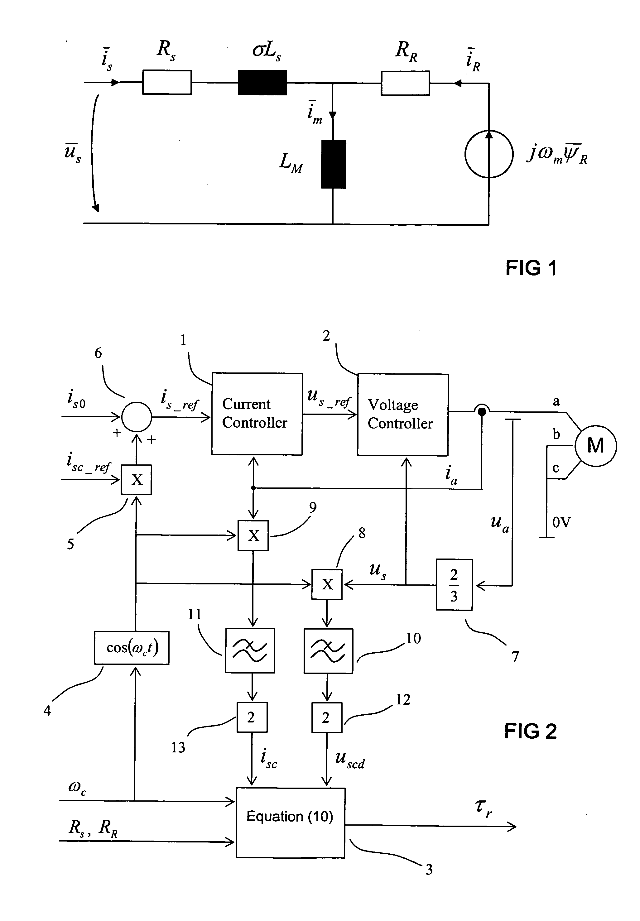
[0012] In FIG. 1, a simple equivalent circuit of an induction machine is shown. The symbols used in FIG. 1 are as follows: {overscore (u)}s is a stator voltage vector, {overscore (i)}s is a stator current vector, iR is a rotor current vector, Rs is stator resistance, RR is rotor resistance, σLs is stray inductance, LM is main inductance and jωm{overscore (ψ)}R is a counter voltage dependent on the rotor flux vector {overscore (ψ)}R and angular speed of the machine ωm.

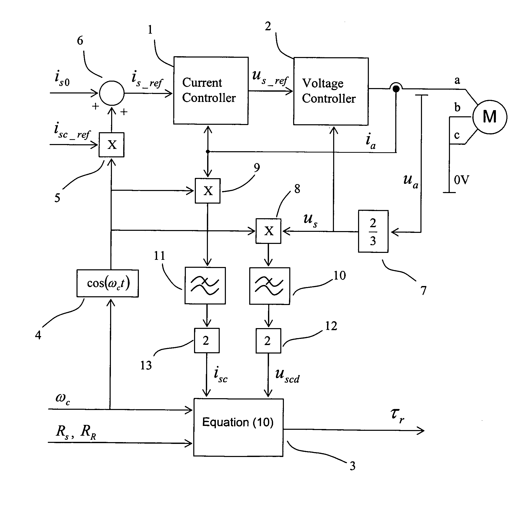
[0013] The method of the invention is used during DC magnetization of the induction machine, and thus the machine is not running. As a starting point for the method, the stator and rotor resistances are known. In the method of the invention, a DC current is fed to the stator of the induction machine and a sine-wave current is added to the stator current. The stator current is then

is=is0+isc cos(ωct),

where

[0014] is0 is the average of the stator current,

[0015] isc is the amplitude of the injected alternating current...


PUM


Abstract

A method for estimating the rotor time constant (τr) of an induction machine when the stator resistance (Rs) and rotor resistance (Rr) of the induction machine are known. The method comprises the steps of feeding a DC current to the stator of the induction machine, injecting a sine-wave current component into the stator of the induction machine, the current having an amplitude (isc) and an angular frequency (ωc), measuring the voltage component (uscd) of the stator voltage of the induction machine in the same direction and with the same angular frequency as the injected current, and calculating the rotor time constant using equation τr=1ωcuscd-Rsisc(Rs+RR)isc-uscd.

Description

RELATED APPLICATION [0001] The present application claims priority under 35 USC § 119 to European Patent Application No. 05104798.3, filed Jun. 2, 2005, the contents of which are hereby incorporated by reference in their entirety. BACKGROUND OF THE INVENTION [0002] The invention relates to a method for estimating the rotor time constant of an induction machine. More specifically, the invention relates to a method which can be used to estimate the rotor time constant during the DC magnetization period of the induction machine prior to the controlled use of the machine. [0003] In a plurality of control methods, the essential parameters of the induction machine are needed for reliable and accurate control of the machine. These parameters include stator and rotor resistances Rs, RR and main and stray inductances LM, σLs. The rotor time constant τr is the ratio between the main inductance and the rotor resistance τr=LM / RR. Thus by estimating the rotor time constant one can calculate the ...

Claims


Application Information

Patent Timeline
IPC IPC(8): H02P3/18
CPCG01R31/34H02P2207/01H02P23/14
Inventor HEIKKILA, SAMULI
Owner OY ABB
Why Eureka
Try Eureka