PFM-PWM DC-DC Converter Providing DC Offset Correction To PWM Error Amplifier And Equalizing Regulated Voltage Conditions When Transitioning Between PFM And PWM Modes

a dc-dc converter and pwm-pwm technology, applied in the direction of electric variable regulation, process and machine control, instruments, etc., can solve the problem of occurrence of dc voltage anomaly in output voltage, and achieve the effect of accurate regulation of converter output voltag

Active Publication Date: 2006-12-07
INTERSIL INC
View PDF5 Cites 145 Cited by
  • Summary
  • Abstract
  • Description
  • Claims
  • Application Information

AI Technical Summary

Benefits of technology

[0008] In accordance with the present invention, this output voltage anomaly problem is successfully obviated by a new and improved dual-mode PWM / PFM DC-DC converter, which incorporates a DC voltage offset correction mechanism in the voltage regulation path of the PWM mode error amplifier. This DC voltage offset correction mechanism allows gain and DC offsets to be nulled and thus set initial conditions to zero. This allows PWM mode to be initiated without need for correction, thus allowing regulation to resume seamlessly. To this end, during PWM mode, this DC voltage offset correction mechanism is operative to impart a DC voltage offset correction, as necessary, into the voltage regulation path through the PWM error amplifier, so as to effectively compensate for or “zero-out” any DC voltage offsets that may be present in the voltage regulation path, thereby enabling the PWM error amplifier to accurately regulate the converter's output voltage. In addition, when the converter transitions between PFM and PWM modes, the DC offset correction mechanism establishes initial conditions of the PWM error amplifier that effectively ensure that the converter's regulated output voltage at the beginning of a new “switched-to” PWM mode cycle is equal to the regulated output voltage at the end of the previous “switched-from” PFM mode cycle. This effectively prevents the occurrence of a DC offset anomaly in the regulated DC output voltage when transitioning between PFM and PWM modes.
[0009] For this purpose, the output of an integrating error amplifier, to which a scaled version of the output voltage is coupled for voltage mode regulation during PWM mode, is coupled as one of two voltage inputs of a DC offset correction circuit and to a transimpedance amplifier. A second voltage input of the correction circuit is coupled to receive the scaled version of the output voltage. During PWM mode, the correction circuit monitors the voltage across the error amplifier and injects a DC offset correction current derived in accordance with this voltage into the output of the transimpedance amplifier. This injected current is reflected back by the transimpedance amplifier as a DC offset correction voltage across its inputs, so that it may be impressed across and charge an integrating capacitor (previously discharged by a controlled shorting switch during PFM mode) of the error amplifier. As a result, the reflected-back voltage across the error amplifier's integrating capacitor effectively compensates for, or “zeroes-out”, any accumulated DC voltage offsets that may be present in the PWM error amplifier circuit's voltage regulation path, so that the error amplifier circuit is able to accurately regulate the converter's output voltage. Once the DC offset correction has stabilized, the DC offset correction circuit stores information representative of the necessary correction.

Problems solved by technology

However, a shortcoming of a conventional dual-mode DC-DC converter is the fact that a difference in initial conditions of the two regulation modes may cause the occurrence of a DC voltage anomaly in the output voltage at the time of switching between the two modes.

Method used


Image

  • PFM-PWM DC-DC Converter Providing DC Offset Correction To PWM Error Amplifier And Equalizing Regulated Voltage Conditions When Transitioning Between PFM And PWM Modes
  • PFM-PWM DC-DC Converter Providing DC Offset Correction To PWM Error Amplifier And Equalizing Regulated Voltage Conditions When Transitioning Between PFM And PWM Modes
  • PFM-PWM DC-DC Converter Providing DC Offset Correction To PWM Error Amplifier And Equalizing Regulated Voltage Conditions When Transitioning Between PFM And PWM Modes

Examples


Embodiment Construction

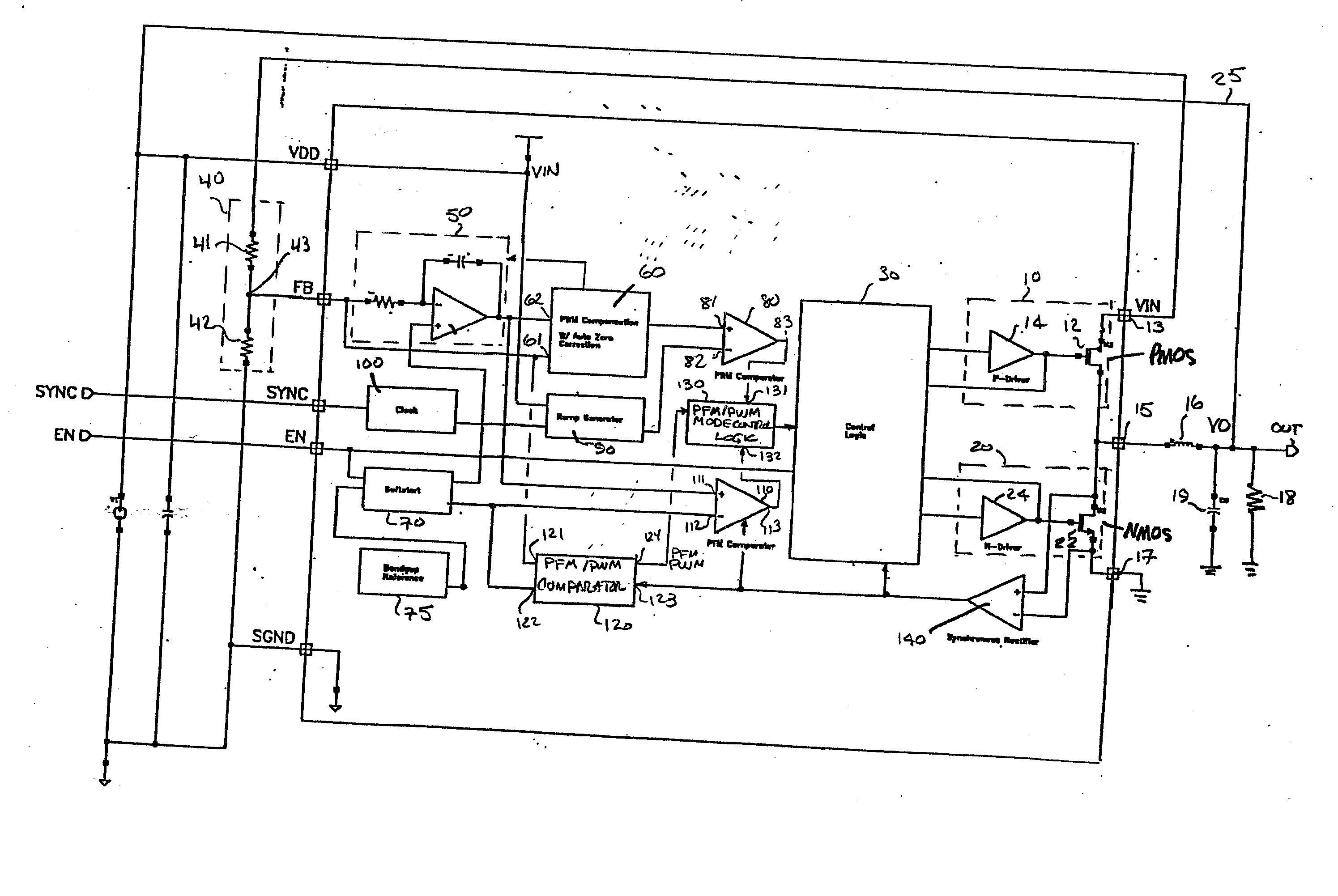
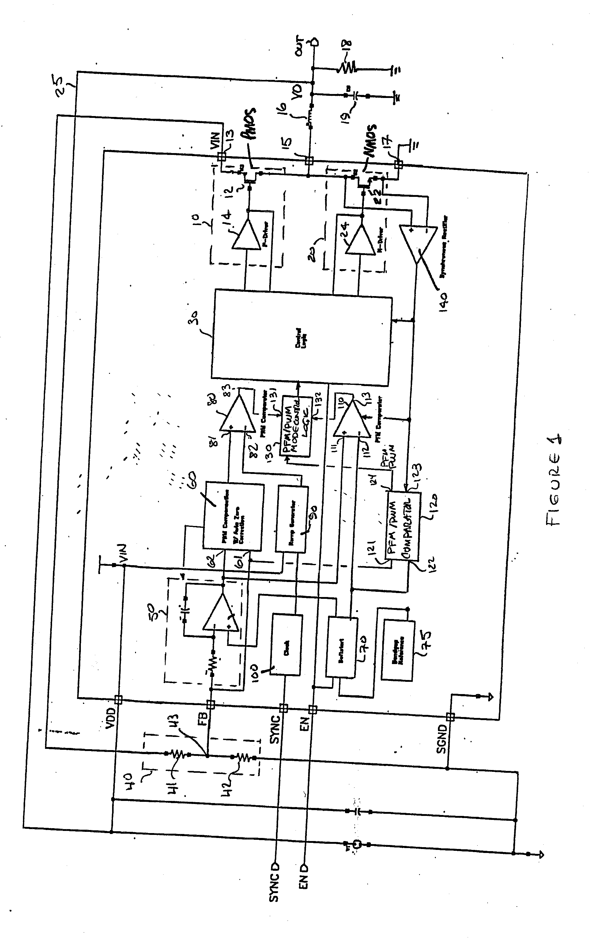
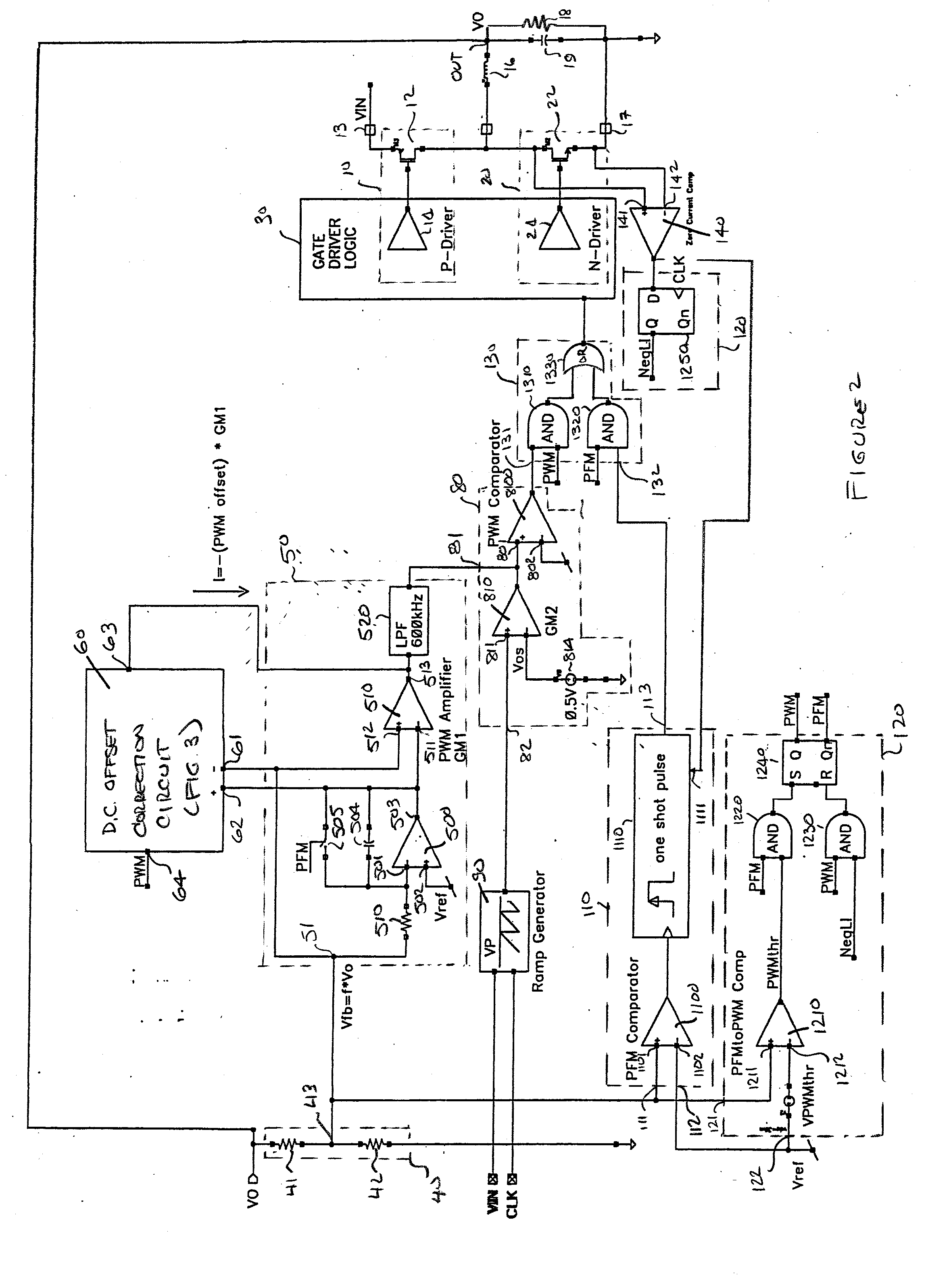
[0018] Before describing the new and improved dual-mode, PFM / PWM based DC-DC converter that employs DC voltage offset correction in accordance with the present invention, it should be observed that the invention resides primarily in a modular arrangement of conventional power supply circuits and electronic signal processing circuits and components therefor. In a practical implementation that facilitates packaging in a hardware-efficient equipment configuration, these modular arrangements may be readily implemented as field programmable gate array (FPGA)-, or application specific integrated circuit (ASIC)-based chip sets. Consequently, the configuration of this modular arrangement of circuits and components and the manner in which they are interfaced with one another have, for the most part, been illustrated in the drawings by readily understandable block diagrams, and associated signal waveforms, which show only those specific details that are pertinent to the present invention, so ...


PUM


Abstract

To prevent a voltage glitch in the regulated DC output voltage of a PWM / PFM DC-DC converter when switching between PFM and PMW modes, the error amplifier of the converter's PWM regulation path is provided with a DC voltage offset correction mechanism. This mechanism “zeros-out” DC voltage offsets that may be present in the voltage regulation path, thereby enabling the error amplifier to accurately regulate the converter's output voltage. When the converter transitions between PFM and PWM modes, the DC offset correction mechanism establishes initial conditions of the error amplifier that effectively ensure that the converter's regulated output voltage at the beginning of a new “switched-to” PWM mode cycle is DC offset-free.

Description

CROSS-REFERENCE TO RELATED APPLICATION [0001] The present application claims the benefit of co-pending U.S. patent application Ser. No. 60 / 688,029, filed Jun. 7, 2005, by T. Groom, entitled: “Auto-Zero Error Amplifier Topology for Dual Mode PFM-PWM DC-to-DC Converter and Associated Methods,” assigned to the assignee of the present application and the disclosure of which is incorporated herein.FIELD OF THE INVENTION [0002] The present invention relates in general to DC power supplies and subsystems thereof, and is more particularly directed to a dual-mode—pulse frequency modulation (PFM) mode and pulse width modulation (PWM) mode—based DC-DC converter, the PWM regulation path error amplifier of which is provided with a DC voltage offset correction mechanism. This DC voltage offset correction mechanism is operative, during PWM mode of operation, to inject a DC voltage offset correction, as necessary, into the voltage regulation path through the PWM path error amplifier, so as to effec...

Claims


Application Information

Patent Timeline
Patent Type & Authority Applications(United States)
IPC IPC(8): G05F1/00
CPCH02M3/157Y02B70/1466H02M2001/0012H02M3/1588H02M1/0012Y02B70/10
Inventor GROOM, TERRY J.
Owner INTERSIL INC
Why Eureka
Try Eureka