Display device and electronic device

Inactive Publication Date: 2006-12-07
SEMICON ENERGY LAB CO LTD
View PDF60 Cites 71 Cited by
  • Summary
  • Abstract
  • Description
  • Claims
  • Application Information

AI Technical Summary

Benefits of technology

[0033] According to the present invention, it is possible to provide a display device superior in visibility by controlling the gray scale number of a display image depending on external li

Problems solved by technology

However, although a liquid crystal display panel has preferable visibility in an indoor environment of 300 to 700 luxes, there is a problem that the visibility is deteriorated significantly in an outdoor environment of 1,000 luxes or more.
There is a liquid crystal panel having a structure where external light is reflected by a pi

Method used


Image

  • Display device and electronic device
  • Display device and electronic device
  • Display device and electronic device

Examples


embodiment mode 1

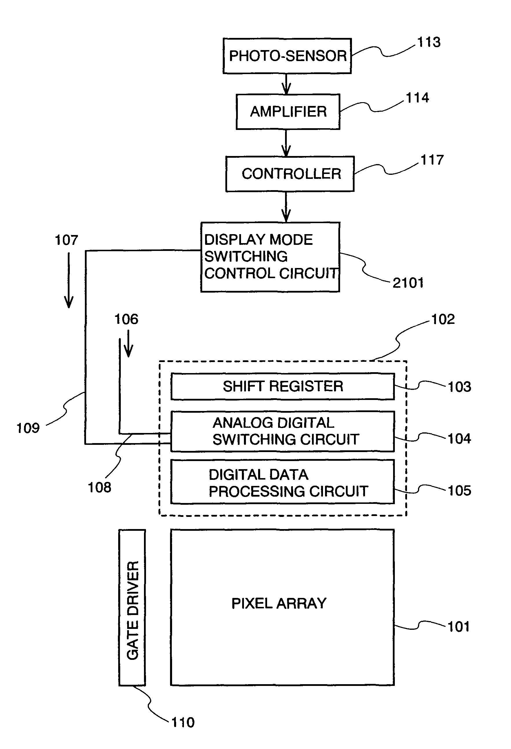
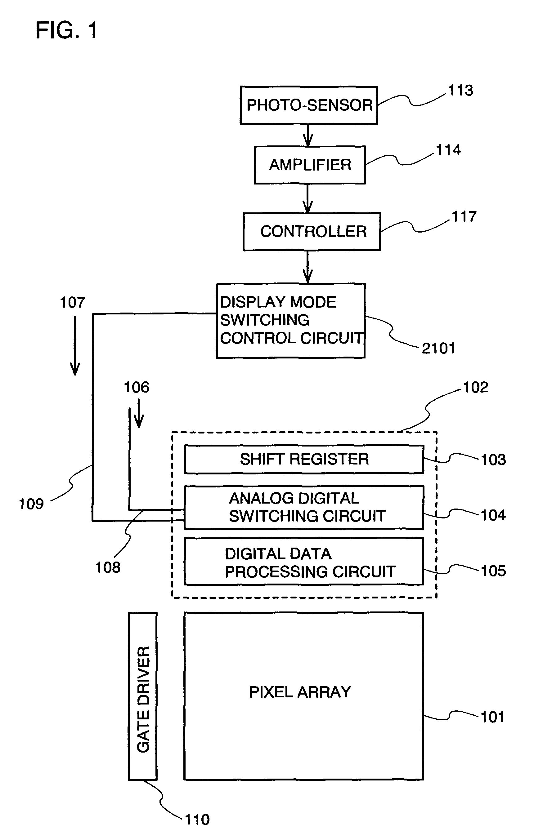
[0081]FIG. 1 shows an overall configuration diagram. A source driver 102 and a gate driver 110 are disposed to drive a pixel array 101. Note that a plurality of the source drivers 102 and gate drivers 110 may each be disposed.

[0082] A photo-sensor 113 detects external light (external light that a display device receives). The output is supplied to an amplifier 114. The amplifier 114 amplifies an electrical signal outputted by the photo-sensor 113, and the amplified electrical signal is supplied to a controller 117. Note that the device can be constituted without the amplifier 114 when the electrical signal outputted by the photo-sensor 113 is sufficiently large.

[0083] The controller 117 controls a display mode switching control circuit 2101. A display mode, the gray scale number, or the like is determined in the display mode switching control circuit 2101. Then, a display mode control signal 107 is controlled by being outputted to the source driver 102.

[0084] The controller 117 c...

embodiment mode 2

[0131] In this embodiment mode, a method for driving a pixel in an analog mode will be described.

[0132]FIGS. 6A and 6B show the relationship between a voltage and a current applied to a driving transistor and a light-emitting element. FIG. 6A shows a circuit of a driving transistor 601 and a light-emitting element 602. The driving transistor 601 and the light-emitting element 602 are connected serially between a wiring 603 and a wiring 604. Since the wiring 603 has a higher potential than that of the wiring 604, a current flows to the light-emitting element 602 from the driving transistor 601.

[0133] The driving transistor 406 in FIG. 4 corresponds to the driving transistor 601 in FIG. 6A, and the light-emitting element 407 in FIG. 4 corresponds to the light-emitting element 602 in FIG. 6A.

[0134]FIG. 6B shows the relationship between a gate-source voltage (or the absolute value thereof) of the driving transistor 60 and a current flowing to the driving transistor 60 and the light-e...

embodiment mode 3

[0143] In this embodiment mode, a method for driving a pixel in a digital mode will be described.

[0144] The relationship between the gate-source voltage (or the absolute value thereof) of the driving transistor 601 and a current flowing to the driving transistor 601 and the light-emitting element 602, shown in FIG. 6B, is referred to. In a digital mode, control is performed in binary like on and off, or H and L. In other words, whether or not a current flows to the light-emitting element 602 is controlled. First, a case where current does not flow is considered. In this case, the gate-source voltage (or the absolute value thereof) of the driving transistor 601 may be 0 V or more as indicated by a voltage 624, a voltage 625, and a voltage 626 and equal to or lower than the threshold voltage of the driving transistor 601.

[0145] Next, a case where current flows is considered. In this case, the driving transistor 601 may be operated in a saturation region, a linear region, or a region...


PUM


Abstract

It is an object of the present invention to provide a display device in which images can be seen under a dark place to intense external light. In the display device, display is performed by changing the gray scale number depending on external light intensity, and display modes can be switched depending on contents displayed on the screen. An analog mode and a digital mode are switched depending on external light intensity. In an analog digital switching circuit, when a video signal is an analog value, a signal is outputted to a pixel array without any change and, when the video signal is a digital value, the signal is outputted to a circuit that performs a digital operation such as a latch circuit. Consequently, display gray scales of a pixel are changed appropriately. Accordingly, a clear image can be displayed. For example, it is possible to ensure visibility in a wide range of a dark place or under indoor florescent light to outdoor sun light.

Description

BACKGROUND OF THE INVENTION [0001] 1. Field of the Invention [0002] The present invention relates to a display device equipped with a screen that displays a character, a still image, a moving image, or the like and relates to a technique to improve visibility of a display screen in various environments where the display device is used. [0003] 2. Description of the Related Art [0004] In recent years, a so-called self-luminous type display device having a pixel that is formed of a light-emitting element such as a light-emitting diode (LED) has been attracting attention. As a light-emitting element used for such a self-luminous type display device, an organic light-emitting diode (OLED) (also called an organic EL element, an electro luminescence: EL element, and the like) has been drawing attention and used for an EL display (for example, an organic EL display or the like). Since a light-emitting element such as an OLED is a self-luminous type, it has advantages such as higher visibili...

Claims


Application Information

Patent Timeline
IPC IPC(8): G09G3/30H05B44/00
CPCG09G3/001H01L27/3269G09G3/3233G09G3/3258G09G3/3291G09G2300/0819G09G2300/0842G09G2300/0852G09G2300/0861G09G2310/0251G09G2310/027G09G2310/0283G09G2310/0289G09G2320/0271G09G2360/144H01L27/3265G09G3/2022H10K59/1216H10K59/13
Inventor YAMAZAKI, SHUNPEIKOYAMA, JUNTANADA, YOSHIFUMIOSAME, MITSUAKIKIMURA, HAJIMEFUKUMOTO, RYOTAYANAI, HIROMI
Owner SEMICON ENERGY LAB CO LTD
Why Eureka
Try Eureka