
Problem diagnosis method and problem repair method for laser device

a laser device and problem repair technology, applied in the direction of instruments, optical apparatus testing, local control/monitoring, etc., can solve the problems of reducing the output, requiring a lot of time to perform repairs, and unable to perform medical treatments, so as to improve the reliability, improve the accuracy, and achieve suitable maintenance work

Inactive Publication Date: 2006-12-07
CYBER LASER
View PDF6 Cites 18 Cited by
  • Summary
  • Abstract
  • Description
  • Claims
  • Application Information

AI Technical Summary

Benefits of technology

[0009] The present invention was made with the purpose of resolving the above-described problems, and offers a problem diagnosis method for a laser device capable of discovering problems such as malfunctions in laser devices at an early stage, thus shortening the time required for maintenance work such as inspection and repair of the laser device. Additionally, the present invention offers a problem repair method for a laser device, for repairing malfunctions or deterioration of parts discovered by the above problem diagnosis method without the need to contact a maintenance worker, thus reducing the cost of repairs.

Problems solved by technology

Additionally, in many models, when there is a decrease in output optical power due to deterioration of the optical parts but within such a range that it is not judged to be an operational anomaly, the input voltage is increased to compensate for the reduction in optical output, as a result of which the optical part which is the cause of the decreased output can be overloaded and thereby irretrievably damaged.
The user often only becomes aware of a malfunction in a device, and can therefore only request repair by a maintenance worker, after the problem has already had an adverse effect on medical or processing work
With the above anomaly detecting methods, a maintenance worker is not contacted until an anomaly occurs in the laser device, so that discovery of a malfunction can be delayed and the laser device can be heavily damaged, thus requiring a lot of time to perform repairs.
For example, if a laser device used for a medical application is severely damaged, it will not be possible to perform the medical treatments until the damage is repaired.
Additionally, when a malfunction occurs, the user is not able to perform repairs and must contact a maintenance worker and wait until the maintenance worker finishes the repairs, thus giving rise not only to repair costs but also to lost opportunity costs as the laser device is left unused during the wait.

Method used


Image

  • Problem diagnosis method and problem repair method for laser device
  • Problem diagnosis method and problem repair method for laser device
  • Problem diagnosis method and problem repair method for laser device

Examples


Embodiment Construction

[0039] Herebelow, preferred embodiments of the problem diagnosis method and problem repair method for a laser device according to the present invention shall be explained in detail with reference to the attached drawings.

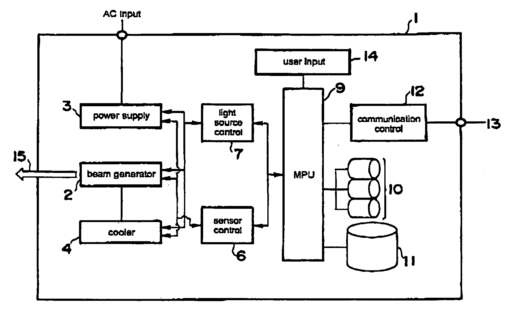
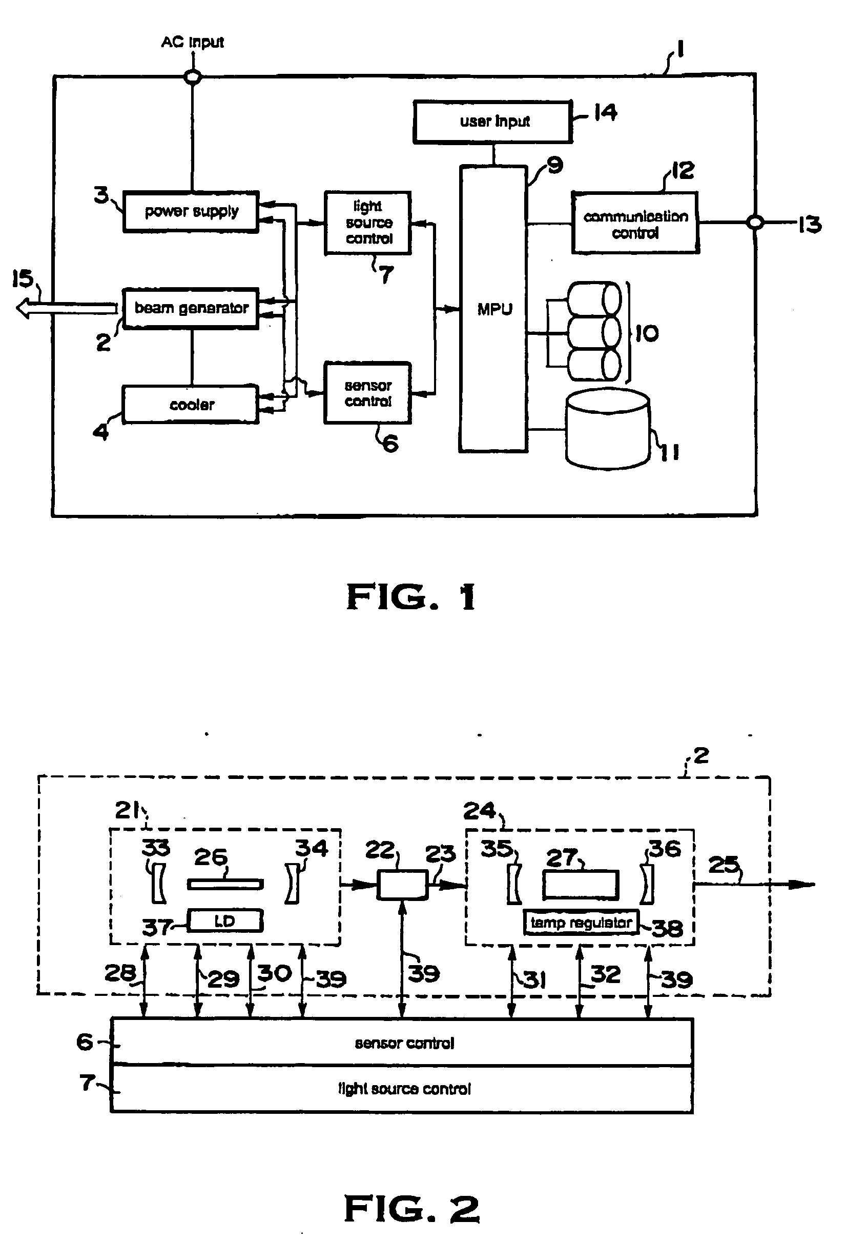
[0040]FIG. 1 is a schematic view showing an example of the structure of a laser device used in the present invention. The laser device mainly comprises a beam generator 2, a power supply portion 3, a cooler 4 and a data managing device. The data managing device comprises a sensor control portion 6, a light source control portion 7, an MPU (microprocessor unit) 9, a memory 10, a high-capacity memory device 11 and a communication control portion 12. The power supply portion 3 supplies electrically driven parts of the laser device with electric power via electric lines that are not shown. The beam generator 2 outputs a laser beam 15. The cooler 4 exchanges heat generated in the beam generator 2.

[0041] The MPU 9 controls the operation of the sensor control portion 6 a...


PUM

PropertyMeasurementUnit
thresholdaaaaaaaaaa
temperatureaaaaaaaaaa
poweraaaaaaaaaa

Abstract

A problem diagnosis method and problem repair method for a laser device such as laser treatment devices used in the medical field and laser processing devices used in industrial fields, capable of detecting problems in laser devices early and reducing the time required for maintenance work on the laser devices are provided. The method comprises a step of measuring the intensity of scattered light generated by an optical part inside the laser device; a step of referring to data indicating a temporal change in the scattered light predicted under predetermined operating conditions of the laser device, and predicting the seriousness of the problem from the intensity of scattered light; and a step of determining what kind of maintenance work is necessary based on the seriousness of the problem. Additionally, the seriousness of the problem in the optical part can be predicted by executing fuzzy logic based on membership functions defining the relationship between scattered light intensity and the seriousness of problems of optical parts.

Description

BACKGROUND OF THE INVENTION [0001] (1) Field of the Invention [0002] The present invention relates to a problem diagnosis method and problem repair method for a laser device and programs for carrying out these methods, and particularly relates to methods for automatically diagnosing and repairing problems in laser devices caused by deterioration of optical parts and the like. For the purposes of this application, the expression “laser device” shall refer broadly to devices that use laser beams for medical, industrial or other applications, including laser treatment devices used in the medical field to perform therapy or surgery on affected parts of the body, or laser processing devices used for processing materials and the like in the industrial field. Additionally, the expression “problem” shall refer generally to situations in which malfunctions or deteriorations occurring in the components of a laser device such as optical parts impairs the ability of the components to perform th...

Claims


Application Information

Patent Timeline
Patent Type & Authority Applications(United States)
IPC IPC(8): H01S3/13H01S3/00B23K26/00G01M11/00G16Z99/00
CPCA61B2018/00636B23K26/03B23K26/032B23K26/034B23K26/403B23K26/428H01S3/1643H01S3/0007H01S3/0014H01S3/0602H01S3/0941H01S3/13G06F19/3412B23K26/707G16H40/40B23K2103/30B23K2103/50A61B2018/00642A61B2018/00672A61B2018/00785A61B2018/00791A61B2018/00863A61B2018/00898G16Z99/00B23K26/60B23K26/70G01B11/00
Inventor WATANABE, AKIRAOKUNO, TADASHITSUGITA, HIROSHISUMIYOSHI, TETSUMISEKITA, HITOSHI
Owner CYBER LASER
Learn More