Method for producing molding shells

a molding shell and thermoset technology, applied in the field of thermoset molding, can solve the problems of affecting the quality of the molding shell, the inability to easily repair the hard shell, and the piping breakage, and achieve the effect of simple and reliable operation and substantially free of corrosion

Inactive Publication Date: 2006-12-07
WEBER MFG TECH INC
View PDF2 Cites 13 Cited by
  • Summary
  • Abstract
  • Description
  • Claims
  • Application Information

AI Technical Summary

Benefits of technology

[0010] It is a further object of the present invention to provide a mold which is simple and reliable in operation and which has an extended cycle life substantially free from corrosion.

Problems solved by technology

During use, corrosion and stress from repeated heating / cooling cycles breaks down the piping and the hard pipe cannot be repaired easily.
The piping has a limited life span of approximately two years, after which time it usually must be removed and replaced with new piping, thereby requiring lengthy rebuilding times at frequent intervals with prolonged shut-down times. Operating and maintenance costs as a result can be expensive.
Heat transfer along the narrow lines of contact between the tubular copper or steel tubing and the planar metal shell normally is not efficient.
Conversely, undesirable heat loss from the mold through the rear concrete fill can be substantial.
This mass absorbs energy from the conventional piping design and exacerbates heat transfer and loss from the rear of the mold.
However, encapsulation of the metal lines is time consuming and expensive.
Also, heat loss from the molds remains significant.

Method used


Image

  • Method for producing molding shells
  • Method for producing molding shells
  • Method for producing molding shells

Examples


Embodiment Construction

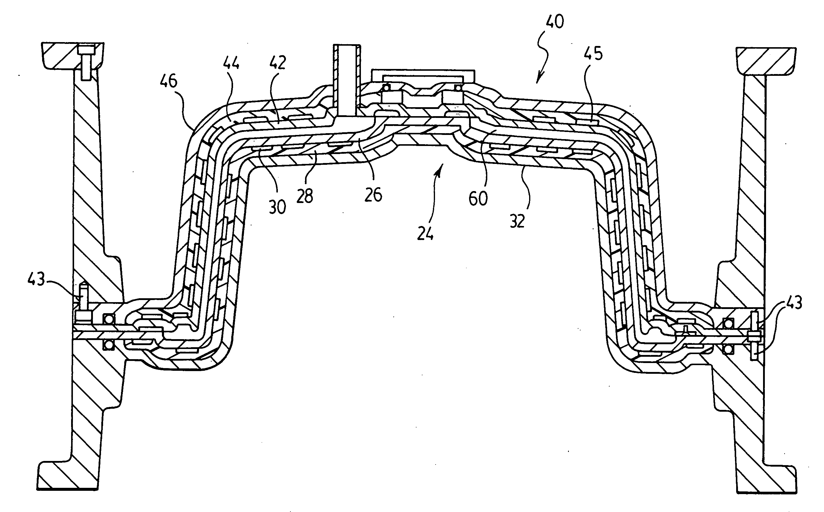
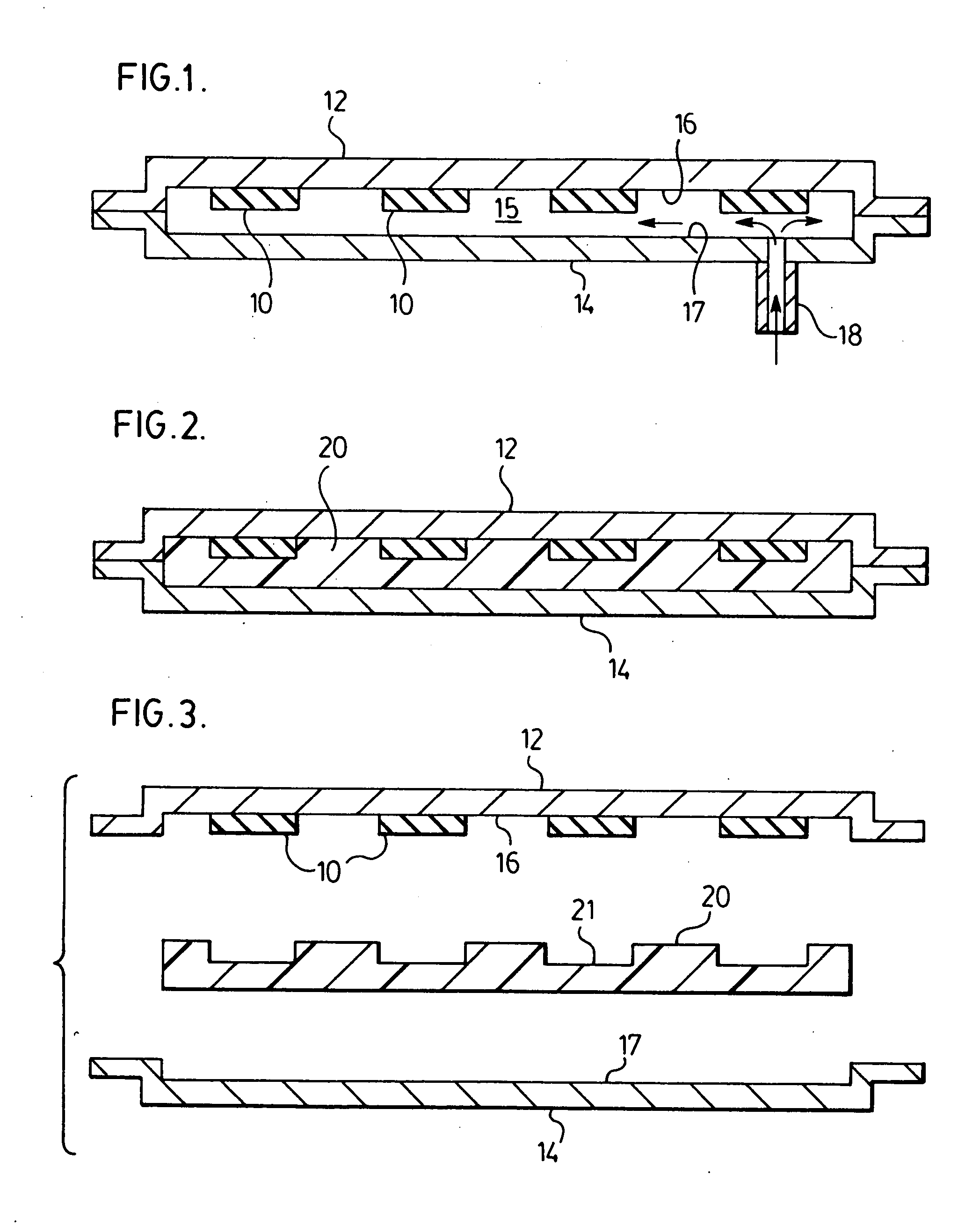
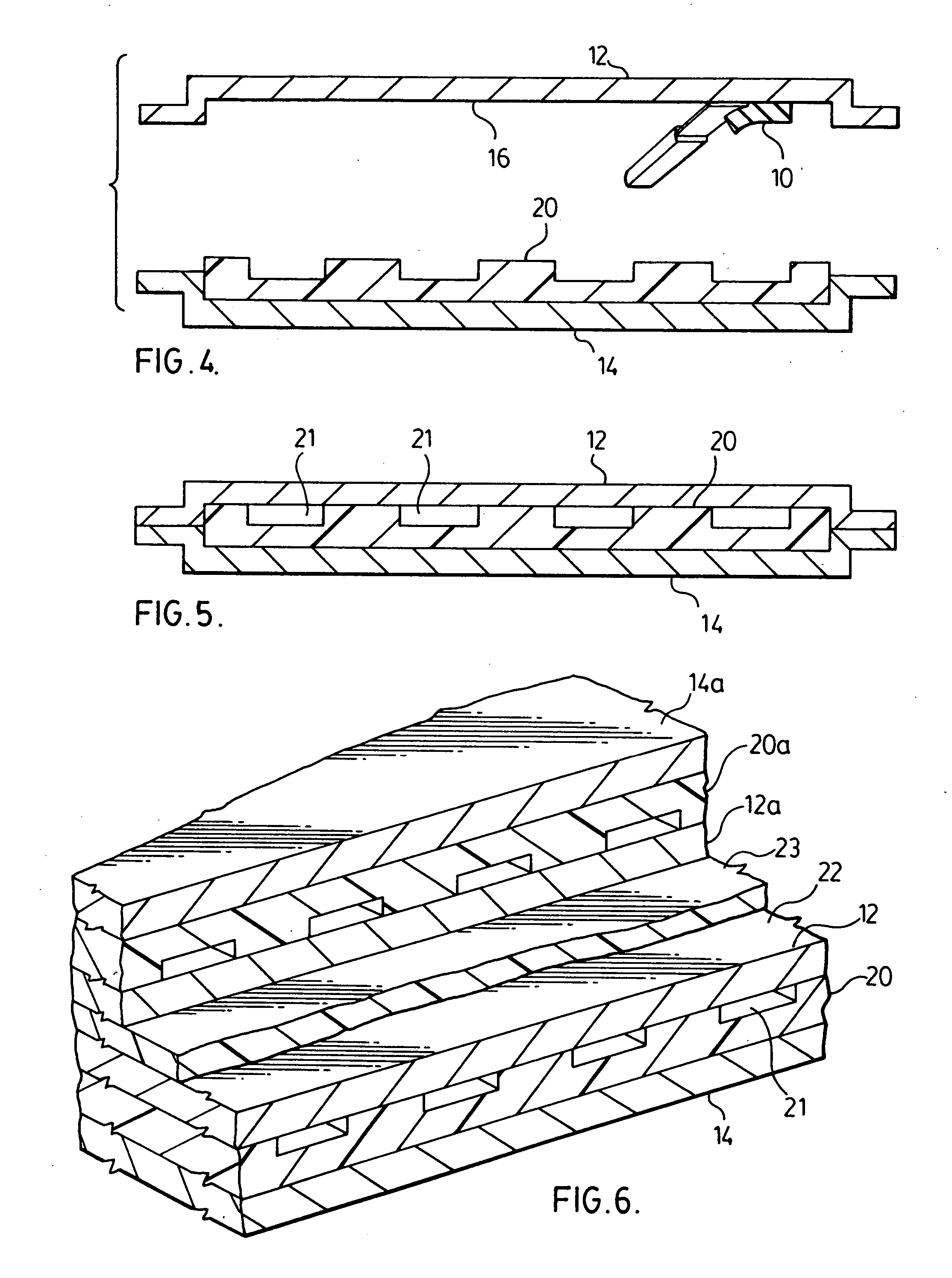
[0031]FIGS. 1-6 illustrate schematically the method of the invention for forming a flexible elastomer polymer fluid jacket with heating / cooling channels. A flexible material such as modelling clay or plastecine is extruded into an elongated channel former 10 having a profile of a desired channel cross-section, preferably about 5 mm thick and 25 mm wide. Channel formers 10 are then adhesively attached to the back of a metal mold shell, such as nickel shell 12, in a continuous or intermittent linear or sinusoidal pattern, as typified in FIGS. 9 and 11. Although the description will proceed with reference to nickel shells, it will be understood that other metal shells such as aluminum or steel shells are contemplated. The support casting 14, preferably a cast aluminum structure, is fastened to the back of the nickel shell 12 to define a space 15 about 10 mm wide between the rear surface 16 of the nickel shell 12 and the opposed surface 17 of the support frame 14. There is thus a design...


PUM

PropertyMeasurementUnit
thickaaaaaaaaaa
thickaaaaaaaaaa
pressureaaaaaaaaaa

Abstract

A method of forming a flexible elastomer polymer fluid jacket for a plastic processing mold, and a novel elastomer polymer fluid jacket. The method comprises attaching channel formers to the rear surface of the metal shells of the mold sections to define a desired flow configuration, securing a support casting to the rear surface of the metal shells spaced from the channel formers to define a designed cavity, feeding a curable elastomer polymer typified by silicone elastomers into the cavity, curing the elastomer polymer, and removing the channel formers whereby the cured elastomer polymer forms a fluid jacket. A mold having mold components with flexible polymer fluid jackets between the mold shells, preferably nickel shells, and support castings permit enhanced heat transfer to the mold cavity while providing improved thermal insulation to the mold. The elastomer polymer also enables multiple modular configurations of the heating and/or cooling function of the mold.

Description

BACKGROUND OF THE INVENTION [0001] (i) Field of the Invention [0002] This invention relates to thermoplastic and thermoset molding and, more particularly, relates to improved heating and cooling channels in thermoplastic and thermoset molds for enhanced heat transfer. [0003] (ii) Description of the Related Art [0004] It is well known to produce metal shells such as nickel shells that are built into molds for injection / compression molding. These shells require heating / cooling lines, typically metal lines, attached to the back of the shell. The metallic lines for these heating / cooling lines are normally copper or steel tubing. The tubing is attached to the shell by various techniques such as welding, soldering, or other mechanical attachment, after machining the shell surface smooth, and the tubing is then encapsulated by a back-fill material such as concrete or epoxy. The shells with encapsulated heating / cooling lines are then mounted on a rear support frame. [0005] The integration o...

Claims


Application Information

Patent Timeline
Patent Type & Authority Applications(United States)
IPC IPC(8): B29C45/00
CPCB29C33/04B29C33/3842B29C45/7312B29C33/565B29C43/52B29C33/405
Inventor BENKOVSZKI, KONRADSHEPPARD, ROBERT E.BRAYSON, ANDREW J.LAFLEUR, RENE J.SCHMITZ, TOM
Owner WEBER MFG TECH INC
Why Eureka
Try Eureka