Method and apparatus for airfoil electroplating, and airfoil

a technology of electroplating and airfoil, which is applied in the direction of cell components, natural mineral layered products, transportation and packaging, etc., can solve the problems of difficult to achieve uniform coating thickness distribution, reduce the variation of platinum aluminide coating thickness, and reduce the thickness of plating.

Inactive Publication Date: 2006-12-07
GENERAL ELECTRIC CO
View PDF21 Cites 17 Cited by
  • Summary
  • Abstract
  • Description
  • Claims
  • Application Information

AI Technical Summary

Benefits of technology

[0004] Therefore, the present invention provides a method and apparatus for reducing variation in platinum aluminide coating thickness by controlling the amount of platinum that is plated on the sections of the part that are submerged deepest in the plating tank. The shield reduces the plating thickness by shielding the surface from current and locally reducing the flow rate of plating electrolyte solution, which results in reduced platinum thickness. By balancing the amount of platinum that is deposited, the shield can accommodate the gradient of aluminum activity within the VPA retort and assist in producing a highly uniform platinum aluminide coating.
[0005] The present invention also provides a means of tailoring and making more uniform the distribution of the platinum thickness, thus reducing platinum aluminide coating cost per part.
[0006] In addition, the present invention improves part performance due to uniform coating thickness and microstructure.
[0007] In accordance with one aspect of the invention, an apparatus is provided including a chemically-nonreactive, electrically-nonconductive shield having a recess generally corresponding to the shape of an airfoil portion to be positioned therein. The shield is submerged in an electroplating solution in a plating tank. The recess in the shield is sized to provide a predetermined, closely-spaced apart clearance between walls of the recess and the adjacent airfoil portion sufficient to reduce the flow rate of an electrolyte present in the electroplating solution between walls of the recess and the adjacent airfoil portion. The clearance permits control of the amount of electroplating that is deposited on the portion of the airfoil that is positioned in the recess in relation to portions of the airfoil not positioned in the recess. The result is a more uniform plating, with minimum plating amounts on all parts of the airfoil.
[0014] In accordance with another aspect of of the invention, an apparatus for use in platinum electroplating a high span turbine blade is provided, and comprises a polytetrafluoroethylene (PTFE) shield having a recess formed therein, the recess having a shape generally corresponding to the shape of high span portions of the blade to be positioned therein. The clearance between the walls of the recess and adjacent airfoil portions is between about 0.10 and 0.13 inches (2.54-7.62 mm) and shields the blade portions from flow currents and thus reduce the flow rate of platinum electrolyte present in an electroplating solution in which the shield and blade portions positioned therein are submerged.

Problems solved by technology

A design challenge that is optimized during the development of a platinum aluminide coating process for a part is to minimize the thickness variation of the coating on the part.
The combined effects of the platinum thickness variation in the plating tank and aluminum activity in the VPA retort have historically made uniform coating thickness distributions hard to achieve.

Method used


Image

  • Method and apparatus for airfoil electroplating, and airfoil
  • Method and apparatus for airfoil electroplating, and airfoil
  • Method and apparatus for airfoil electroplating, and airfoil

Examples


Embodiment Construction

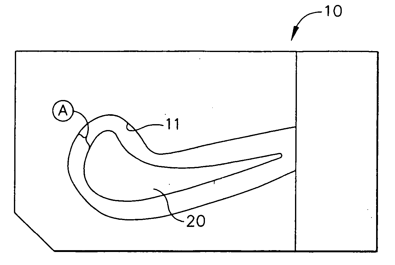
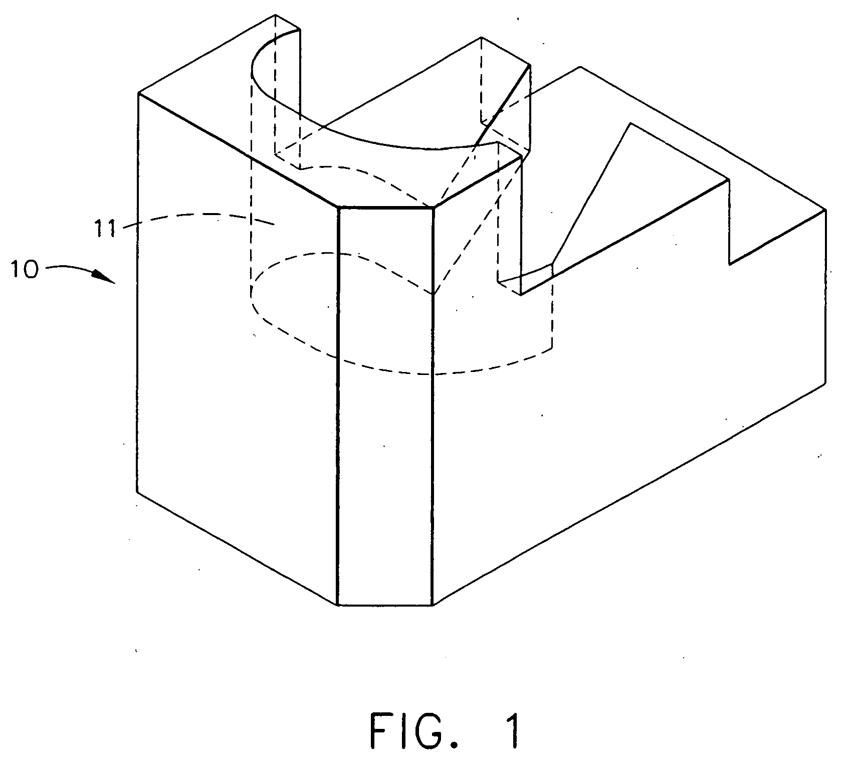
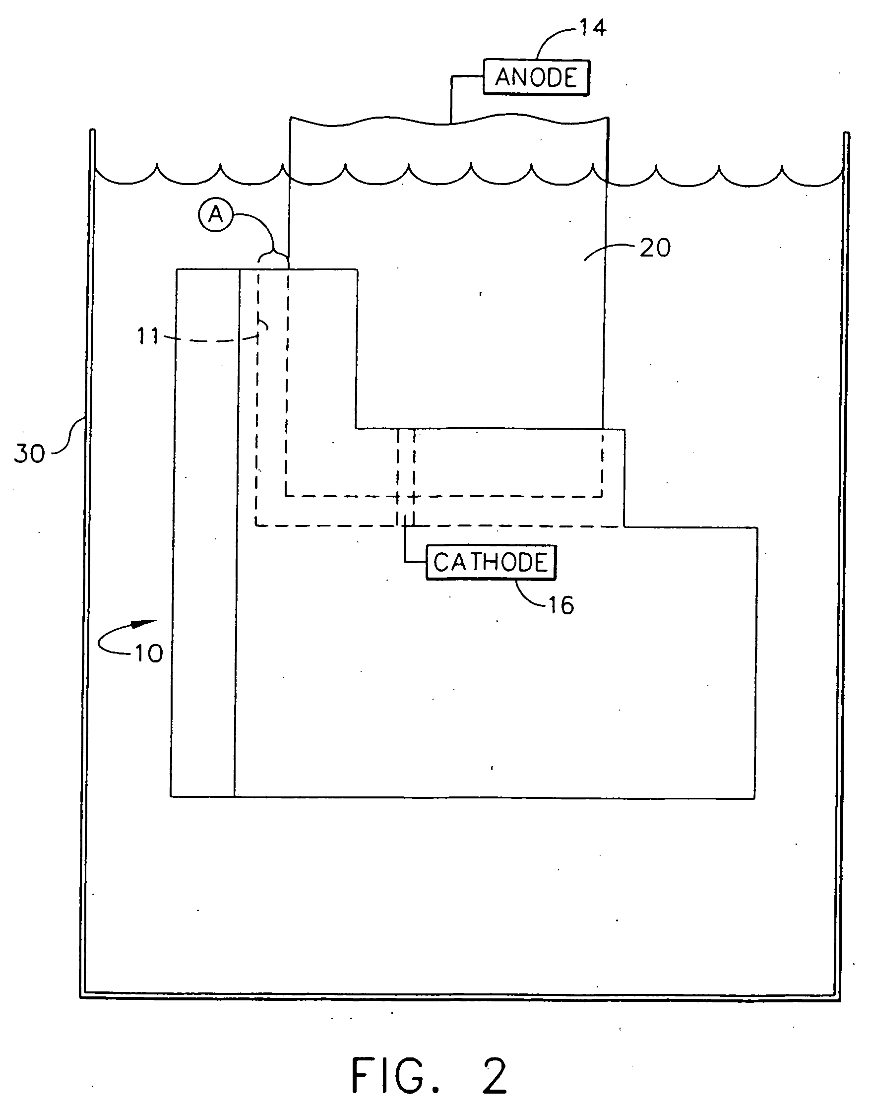
[0026] Referring now specifically to the drawings, an electroplating airfoil shield according to the present invention is illustrated in FIGS. 1 and 2, and shown generally at reference numeral 10. The use of the shield 10 produces a tailored platinum distribution on the surface of the high span regions of the part that is to be platinum aluminide coated. According to one preferred embodiment of the invention, the shield 10 is fabricated from a solid block of polytetrafluoroethylene (PTFE). This material provides the shield 10 with both chemically-nonreactive and electrically-nonconductive characteristics. An electrically-nonconductive material such as PTFE is necessary because, otherwise, the thickness distribution of the platinum layer would degrade instead of improve.

[0027] A recess 11 is machined into the shield 10 by to provide a predetermined clearance to all adjacent surfaces of a turbine blade 20 to be electroplated. The required blade-to-shield clearance is empirically dete...


PUM

PropertyMeasurementUnit
thickaaaaaaaaaa
thicknessaaaaaaaaaa
thicknessaaaaaaaaaa

Abstract

A chemically-nonreactive, electrically-nonconductive shield having a recess generally corresponding to the shape of an airfoil portion to be positioned therein. The shield is submerged in an electroplating solution in a plating tank. The recess in the shield is sized to provide a predetermined, closely-spaced apart clearance between walls of the recess and the adjacent airfoil portion sufficient to reduce the flow rate of an electrolyte present in the electroplating solution between walls of the recess and the adjacent airfoil portion. The clearance permits control of the amount of electroplating that is deposited on the portion of the airfoil that is positioned in the recess in relation to portions of the airfoil not positioned in the recess.

Description

TECHNICAL FIELD AND BACKGROUND OF THE INVENTION [0001] This invention relates to a method and apparatus for airfoil electroplating, and an airfoil with enhanced electroplating thickness and uniformity. The method and apparatus have particular application in regulating and controlling the deposited thickness of platinum and other platinum group metals on high span regions of turbine airfoil components during the platinum electroplating process. [0002] Platinum aluminide coatings are applied to turbine components to provide environmental protection of the nickel substrate base metal. The application of platinum aluminide coatings is a three-step process that includes electroplating, diffusion heat treatment and aluminiding. During electroplating, platinum is plated over the surface of the component to be coated. Diffusion heat treatment creates a metallurgical bond between the nickel substrate and the layer of platinum. Aluminiding is conducted in a furnace at elevated temperatures wh...

Claims


Application Information

Patent Timeline
Patent Type & Authority Applications(United States)
IPC IPC(8): B32B19/00B32B9/00B32B15/01
CPCC25D17/008Y10T428/12736Y10S204/07
Inventor RUCKER, MICHAELGUPTA, BHUPENDRA K.
Owner GENERAL ELECTRIC CO
Why Eureka
Try Eureka