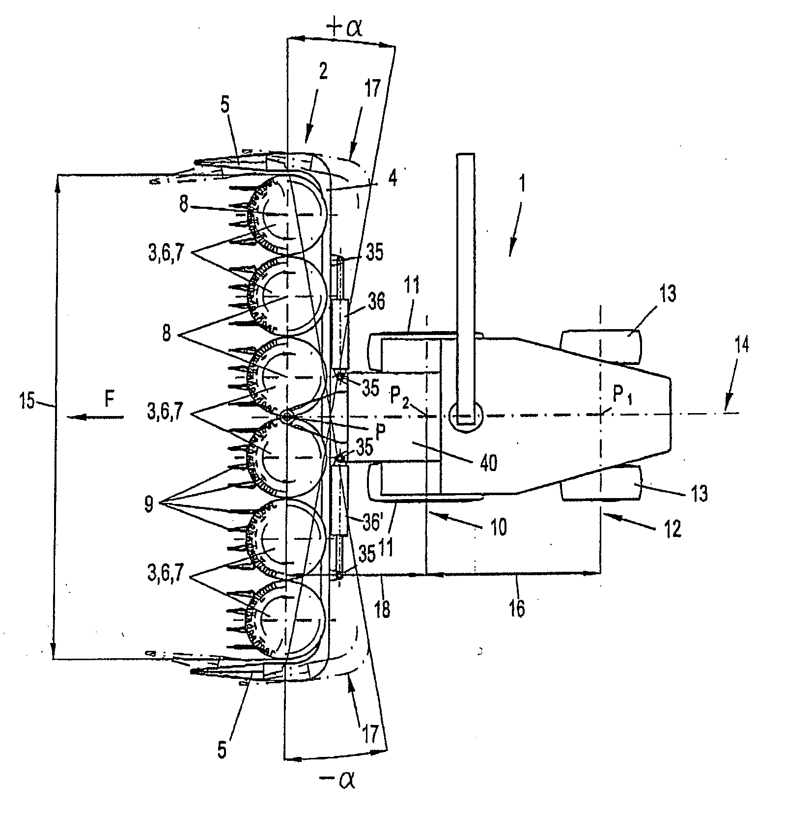
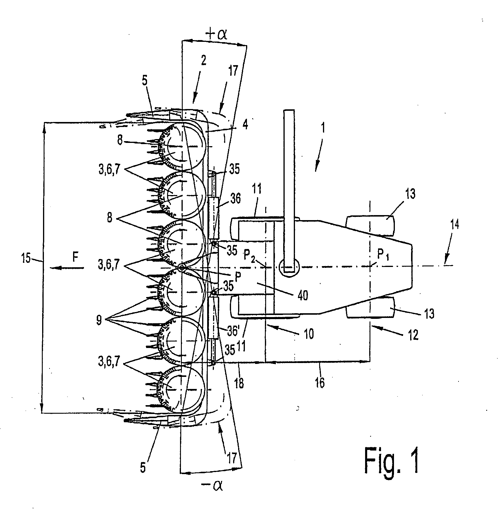
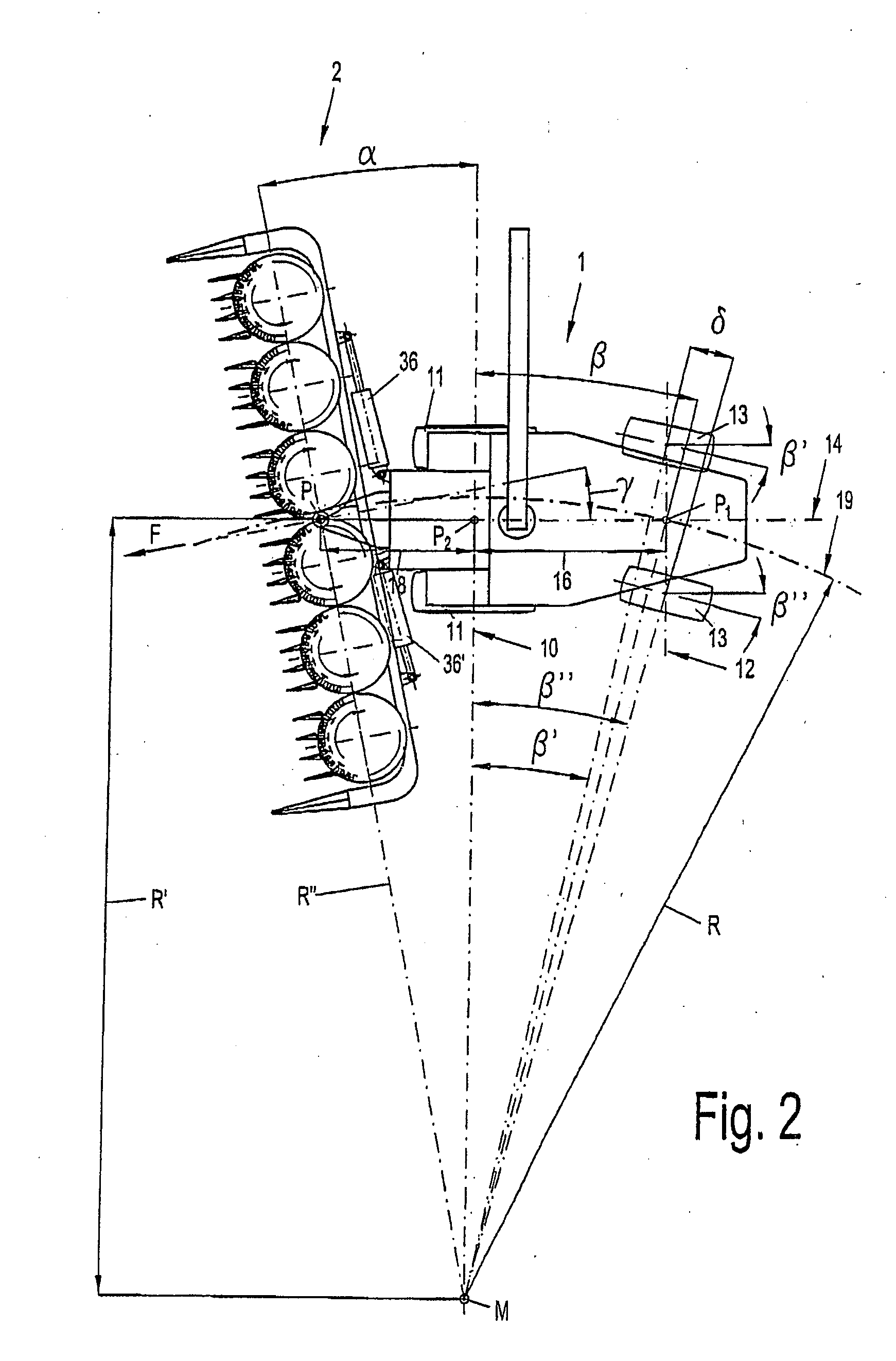
Method and device for operating an attachment for harvesting stalk-like crops

a technology of stalk-like crops and attachments, which is applied in the direction of control devices, outside dividers, mowers, etc., can solve the problems of laborious turning maneuvers, increased stubble length, and loss of harvested crops

Inactive Publication Date: 2006-12-14
CLAAS SAULGAU
View PDF25 Cites 10 Cited by
  • Summary
  • Abstract
  • Description
  • Claims
  • Application Information

AI Technical Summary

Benefits of technology

[0010] These orientation changes of the stalk-guiding elements are pivoting movements that take place relative to the carrier vehicle about one or more upright axes of rotation. These pivoting movements are defined by the pivot angle about precisely this pivot axis. The magnitude of the pivoting movement is indicated by the angle of inclination, and it is dependent on the amount of the turning radius being passed through at a particular instant. As an alternative, the angle of inclination may also be derived directly from the steering angle of the steering of the carrier vehicle.
[0011] In the ideal case, each of the stalk-guiding elements can be pivoted separately and independently of another, in each case about its own upright pivot axis, but it is also possible for the entire attachment to be able to be pivoted relative to the carrier vehicle, so that all of the stalk-guiding elements of an attachment are pivoted about a common upright pivot axis. If the latter is the case, this is an averaged correction of the angle of inclination which, in practice, supplies sufficiently good results. However, according to the present invention, it is also possible to bring about the angle of inclination or the angles of inclination of a guiding element by means of a combination of pivoting movements such that, firstly, the entire attachment is pivoted by a partial angle of inclination relative to the carrier vehicle and, secondly, the stalk-guiding elements are pivoted individually or in groups by a further partial angle of inclination. One group of stalk-guiding fingers, as stalk-guiding elements, may be arranged, for example, on a common base of a single cutting and conveying rotor, with the result that the base can be pivoted together with the guiding elements. The sum total of both partial angles of inclination in turn produces the angle of inclination of the respective stalk-guiding element during the particular cornering operation.
[0012] The angle of inclination itself is determined from the angle of lock of the steering wheels of the carrier vehicle, as is well known to the person skilled in the art, for example, from the technical teaching of automatic steering systems of carrier vehicles in the case of field choppers or combine harvesters. The value of this angle of lock is supplied to a microprocessor as an input signal from which the angle of inclination or the angles of inclination of the stalk-guiding elements is / are then calculated and supplied as a corresponding output signal to one or more actuators, which then cause the pivoting operation of the stalk-guiding elements by a corresponding angle of inclination. An actuator may be, for example, a hydraulically or an electrically actuated pivoting drive and, in a particularly advantageous manner, a hydraulic cylinder.
[0013] In this case, it may be advantageous if at least one actuator is likewise equipped with a sensor which supplies conclusions concerning the state of the angle of inclination of the stalk-guiding elements, where this value is also supplied to a microprocessor as an input signal. The adjustment of the angle of inclination or angles of inclination of the stalk-guiding elements can therefore be actively assigned to the automatic steering system of the carrier vehicle in the sense of a control circuit.
[0014] In the subsequent straight-ahead travel, the pivoting operation of the stalk-guiding elements is therefore neutralized again, i.e., the angles of inclination are again returned to the value zero.
[0015] The particular advantage of the present invention therefore resides in the fact that at least one stalk-guiding element, as directing element, can be pivoted relative to the carrier vehicle as a function of the location or the position of the attachment. Therefore, at least one stalk-guiding element of the attachment can execute a relative rotation about a center of motion within the context of a rotation or pivoting by the amount of an angle of inclination as a consequence of a change in direction of travel of the attachment and / or of the carrier vehicle. In this case, however, the entire attachment or parts of the attachment may also participate in the pivoting.

Problems solved by technology

As a result, when they come into contact with the plants which are still upright, they cause the stalks thereof to bend over by displacing them transversely, with the consequence that the stalk is cut off obliquely in an inclined position and the length of the stubble is thereby increased, which causes losses in the harvested crop.
If this is to be avoided, a laborious turning maneuver is required, generally associated with dragging or traveling forward and backward.
Identical problems occur when working on sloping terrain if slope drift arises, and the carrier vehicle positions itself obliquely with respect to the direction of travel as a consequence of the drift forces.
Even in this case, the stalk-guiding elements, which are mounted upstream of the working tools and are situated obliquely with respect to the direction of travel, tend to bend the plant stalks out of the upright position which then results in relatively long stubble lengths.

Method used


Image

  • Method and device for operating an attachment for harvesting stalk-like crops
  • Method and device for operating an attachment for harvesting stalk-like crops
  • Method and device for operating an attachment for harvesting stalk-like crops

Examples


Embodiment Construction

[0024]FIG. 1 shows a self-propelled harvesting machine according to the present invention in a top plan view, including a carrier vehicle 1, realized as a field chopper with an attachment 2 (corn picker head) which is known for harvesting entire corn plants which, after cutting and further transportation, are supplied to the draw-in gap and are drawn in by the draw-in rollers and are therefore supplied to the chopping drum. The attachment comprises a machine frame 4 with the cutting and conveying rotors 3 which are driven in a revolving manner about upright axis of rotation 8 and have cutter and conveying disks 6, 7 which are arranged coaxially with the axis of rotation 8 and are situated one above the other and are mounted in the machine frame 4. The attachment is outwardly bounded by dividers 5 which are situated partly upstream from and partly next to the outer cutting and conveying rotors, and which at the same time delimit the cutting and working width 15 situated in between. M...


PUM


Abstract

A method for operating an attachment for harvesting stalk-like crops mounted on a carrier vehicle including a plurality of working tools and at least one stalk-guiding element mounted upstream from the working tools, the method including a step of causing the at least one stalk-guiding element to pivot as a function of the location or position of at least one of the attachment and the carrier vehicle.

Description

[0001] This application claims the benefit under 37 CFR §119(a)-(d) of German Application No. 10 2005 027 586.9 filed Jun. 14, 2005, the entirety of which is incorporated herein by reference. FIELD OF THE INVENTION [0002] The invention relates to a method and a device for operating an attachment for harvesting stalk-like crops. BACKGROUND OF THE INVENTION [0003] In conjunction with field choppers and their attachments, cutting and conveying devices for cutting stalk-like stem crops, such as, for example, corn, with cutting and conveying tools revolving about upright axes are known. [0004] Exemplary embodiments of a revolvingly driven cutting and conveying system of attachments for harvesting stalk-like crops are known, for example, from DE 102 805 and DE 102 30 236. These types of attachments are held on the front side of field choppers, cut off the stalk-like plants close to the ground, convey them into the draw-in shaft of the chopper. [0005] The cutting and conveying device descr...

Claims


Application Information

Patent Timeline
Patent Type & Authority Applications(United States)
IPC IPC(8): A01D45/02
CPCA01D63/00A01D43/082
Inventor RAUCH, HANS
Owner CLAAS SAULGAU
Why Eureka
Try Eureka