Image processing apparatus, image processing method, computer program, and storage medium

a technology of image processing and image area, applied in the field of image processing apparatus and image processing method, can solve the problems of increasing the power consumption of a battery, poor color tone of an eye, damage to the facial expression of the subject, etc., and achieve the effect of accurate detection of an image area and poor color ton

Active Publication Date: 2006-12-14
CANON KK
View PDF14 Cites 45 Cited by
  • Summary
  • Abstract
  • Description
  • Claims
  • Application Information

AI Technical Summary

Benefits of technology

[0024] It is desirable to accurately detect an image area having poor color tone.

Problems solved by technology

It is well known that flash photography can cause poor color tone of an eye, which is widely known as the red eye effect.
This is an important challenge.
However, this method undesirably increases the power consumption of a battery, compared with normal image capturing, and the preflash can damage the facial expression of the subject.
Although such an operation is relatively easily performed in, for example, a personal computer system provided with a large display device, it is not easy to perform the operation of enlarging an image and scrolling the enlarged image to specify a correction area in an apparatus, such as a digital camera or a printer, provided with a small area display device.
However, the proposed methods of automatically correcting the red eye effect have the following problems.
Accordingly, it is difficult to employ such a detection method in a system built in a digital camera or a printer, although the method is suitable for processing in a personal computer including a high-performance CPU operating at a clock rate of several gigahertz and having a memory capacity of several hundred megabytes.
However, the determination on the basis of the saturation is not necessarily suitable for persons having the eyes of darker pigment.
In other words, it may be impossible to determine the pixels corresponding to the red eye area depending on subjects even in view of the saturation.

Method used


Image

  • Image processing apparatus, image processing method, computer program, and storage medium
  • Image processing apparatus, image processing method, computer program, and storage medium
  • Image processing apparatus, image processing method, computer program, and storage medium

Examples


first embodiment

Structure

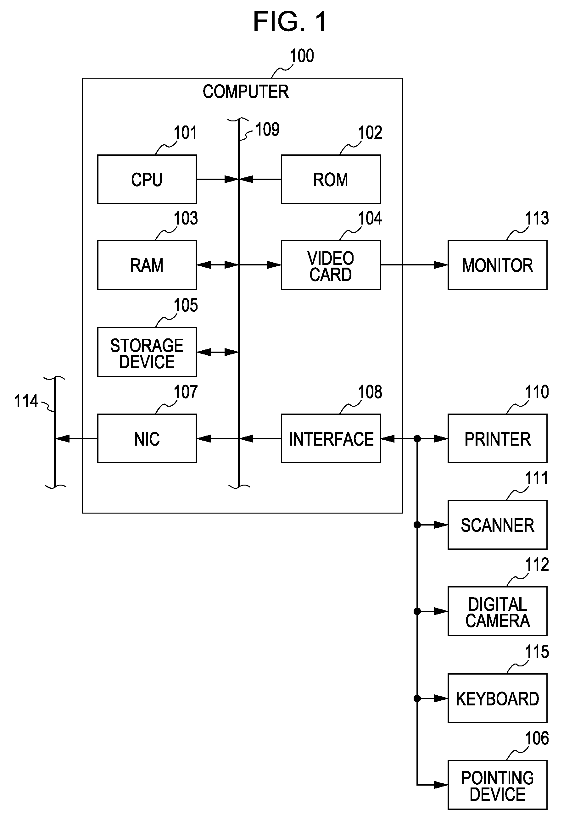
[0078]FIG. 1 is a block diagram showing an example of the structure of a computer (an image processing apparatus) performing the image processing according to a first embodiment of the present invention.

[0079] A computer 100 includes a central processing unit (CPU) 101, a read only memory (ROM) 102, a random access memory (RAM) 103, a video card 104 connected to a monitor 113 (the monitor 113 may include a touch panel), a storage device 105, such as a hard disk drive or a memory card, a serial bus interface 108 conforming to universal serial bus (USB) or IEEE 1394, and a network interface card (NIC) 107 connected to a network 114. The above components are connected to each other via a system bus 109. A pointing device 106, such as a mouse, a stylus, or a tablet, a keyboard 115, and so on are connected to the interface 108. A printer 110, a scanner 111, a digital camera 112, etc. may be connected to the interface 108.

[0080] The CPU 101 can load programs (including progra...

second embodiment

[0194] Image processing according to a second embodiment of the present invention will now be described. The same reference numerals are used in the second embodiment to identify approximately the same components as in the first embodiment. A detailed description of such components is omitted herein.

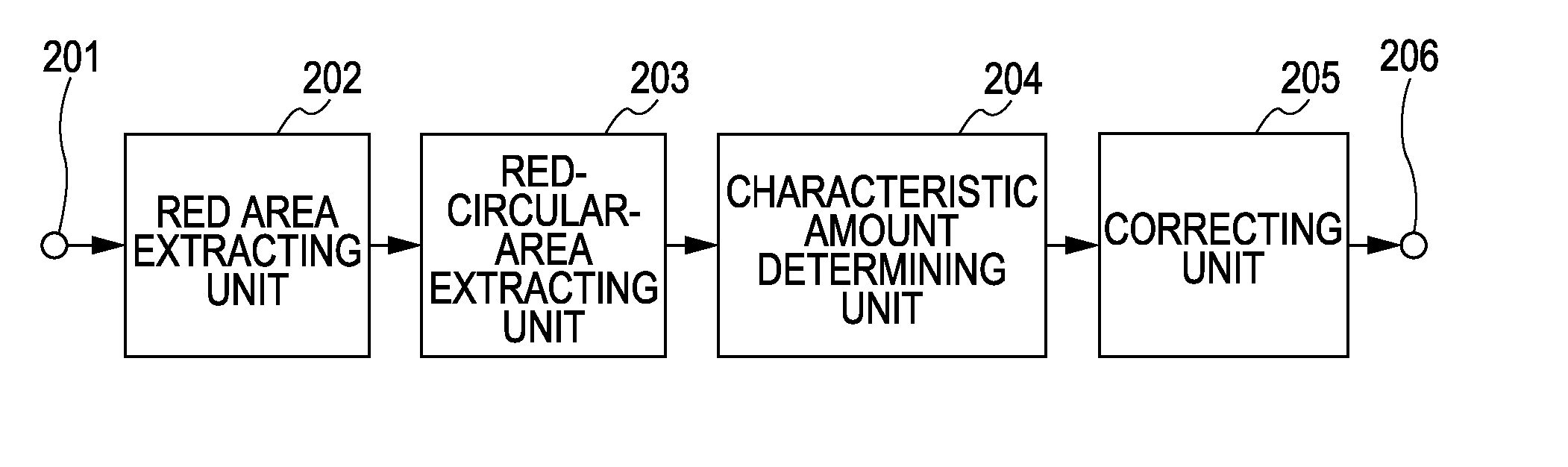
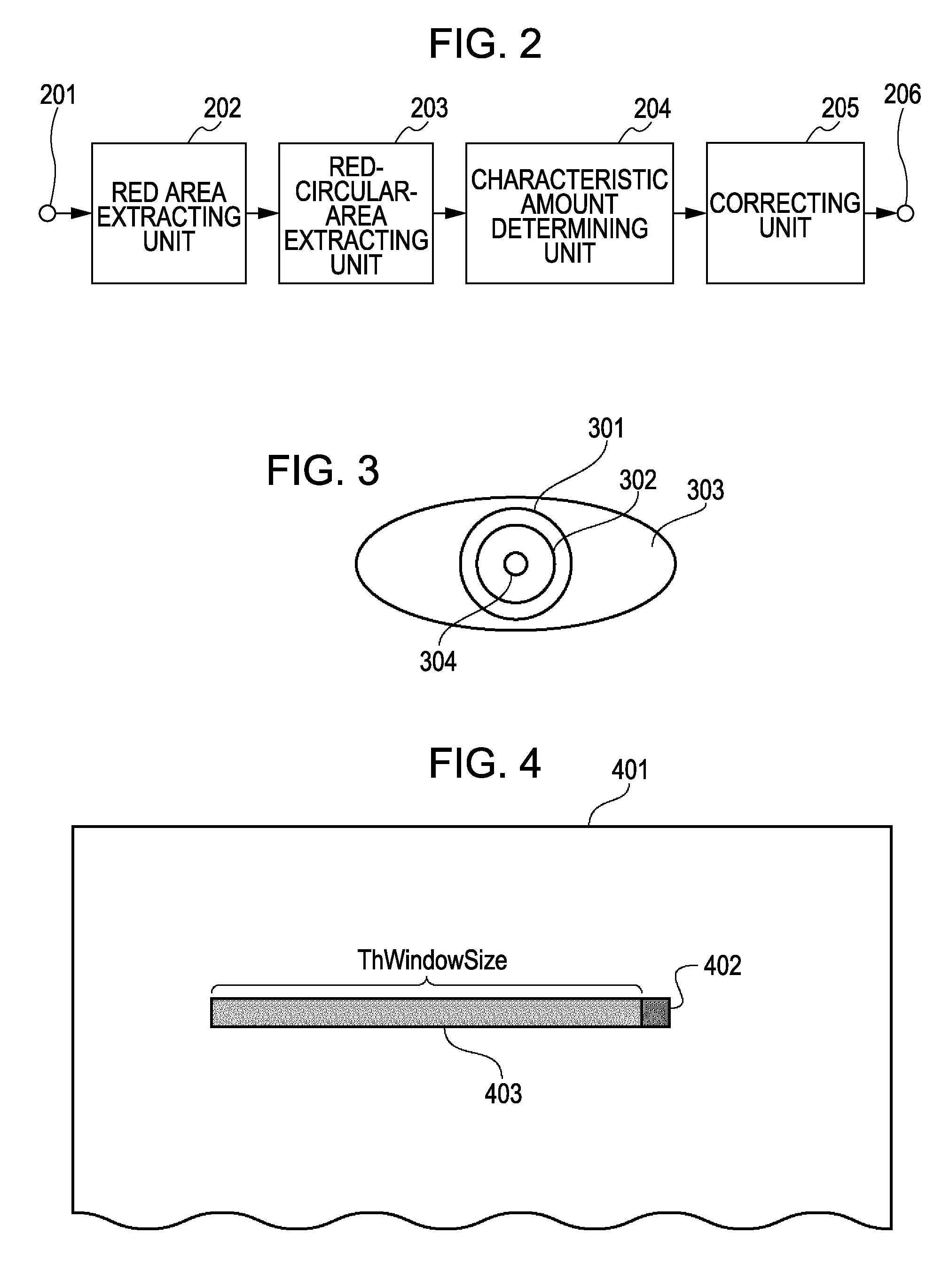
[0195] In the adaptive binarization described above in the first embodiment of the present invention, the window area 403 (refer to FIG. 4) having a predetermined size is set at the left of the target pixel (ahead of the primary scanning direction), the average Er(ave) of the evaluation amounts of the pixels in the window area 403 is calculated, and the binarization is performed by using the average Er(ave) as the threshold value depending on whether target pixel is in the red area. The number of pixels that are referred to to calculate the threshold value is small in such a method, thus increasing the speed of the processing. However, since the window area 403 is set only at the left o...

third embodiment

[0205] Image processing according to a third embodiment of the present invention will now be described. The same reference numerals are used in the third embodiment to identify approximately the same components as in the first and second embodiments. A detailed description of such components is omitted herein.

[0206] Methods of extracting a pixel in the red area by the adaptive binarization on the basis of the red evaluation amount Er defined in Equation (3) are described in the first and second embodiments of the present invention. With such methods, pixels corresponding to the outer or inner corner 2302 of the eye are possibly detected as the pixels in the red area, in addition to the pupil 2301 of the red eye shown in FIG. 23. Enlargement of the outer or inner corner 2302 of the eye shows that many “dark red” pixels having, for example, a pixel value (R,G,B)=(81,41,31) exist. The red evaluation amount Er of these pixels is equal to 49%, which is a relatively large value. Accordin...


PUM


Abstract

An image processing apparatus includes a calculating unit configured to calculate an evaluation amount of poor color tone for every pixel in an image and an extracting unit configured to extract a candidate pixel having the poor color tone on the basis of the evaluation amount. The evaluation amount is calculated from red and green components of the image.

Description

BACKGROUND OF THE INVENTION [0001] 1. Field of the Invention [0002] The present invention relates to an image processing apparatus and an image processing method. For example, the present invention relates to image processing for detection of an image area having poor color tone of an eye (red-eye). [0003] 2. Description of the Related Art [0004] It is well known that flash photography can cause poor color tone of an eye, which is widely known as the red eye effect. The red eye effect is a phenomenon caused by light that is emitted from a flash and incident on an open pupil and that illuminates the retina at the interior back of the eye. The light reflected from the back of the retina brings the red of the capillary blood vessels into an image of a human being or an animal, such as a dog or a cat, captured by using the flash under poorly illuminated conditions. It is likely to cause the red eye effect in the case of persons having the eyes of lighter pigment because the transmittanc...

Claims


Application Information

Patent Timeline
Patent Type & Authority Applications(United States)
IPC IPC(8): G06K9/00
CPCG06K9/0061G06T7/408G06T2207/30201G06T7/0085H04N1/624G06T5/005G06T5/20G06T2207/30216G06T7/13G06T7/90G06V40/193G06T5/00G06T5/10
Inventor UMEDA, KIYOSHI
Owner CANON KK
Why Eureka
Try Eureka