Light Emitting Module and Single-Fiber Two-Way Optical Communication Module

a light-emitting module and optical communication technology, applied in the field of light-emitting modules and single-fiber two-way optical communication modules, can solve the problems of low coupling efficiency of optical communication modules, low light-emitting efficiency of light-emitting modules, etc., to achieve efficient entry of optical fibers, reduce the amount of axis shift in a plane direction perpendicular to the optical axis

Inactive Publication Date: 2006-12-14
NTT ELECTORNICS CORP
View PDF9 Cites 28 Cited by
  • Summary
  • Abstract
  • Description
  • Claims
  • Application Information

AI Technical Summary

Benefits of technology

[0008] To solve the problem, an object of the present invention is to provide a light emitting module and a single-fiber two-way optical communication module realizing improved light coupling efficiency.

Problems solved by technology

Since an optical filter is inserted in nonparallel rays, aberration occurs and the coupling efficiency is low.
Accordingly, the light coupling efficiency of the optical communication module is low.
Since the optical axis direction of the light receiving module is not adjusted, light receiving efficiency of the light receiving module is low.

Method used


Image

  • Light Emitting Module and Single-Fiber Two-Way Optical Communication Module
  • Light Emitting Module and Single-Fiber Two-Way Optical Communication Module
  • Light Emitting Module and Single-Fiber Two-Way Optical Communication Module

Examples


Embodiment Construction

[0030] Embodiments of the present invention will be described with reference to the attached drawings. The embodiments described below relate to examples of the configuration of the present invention, and the present invention is not limited to the following embodiments.

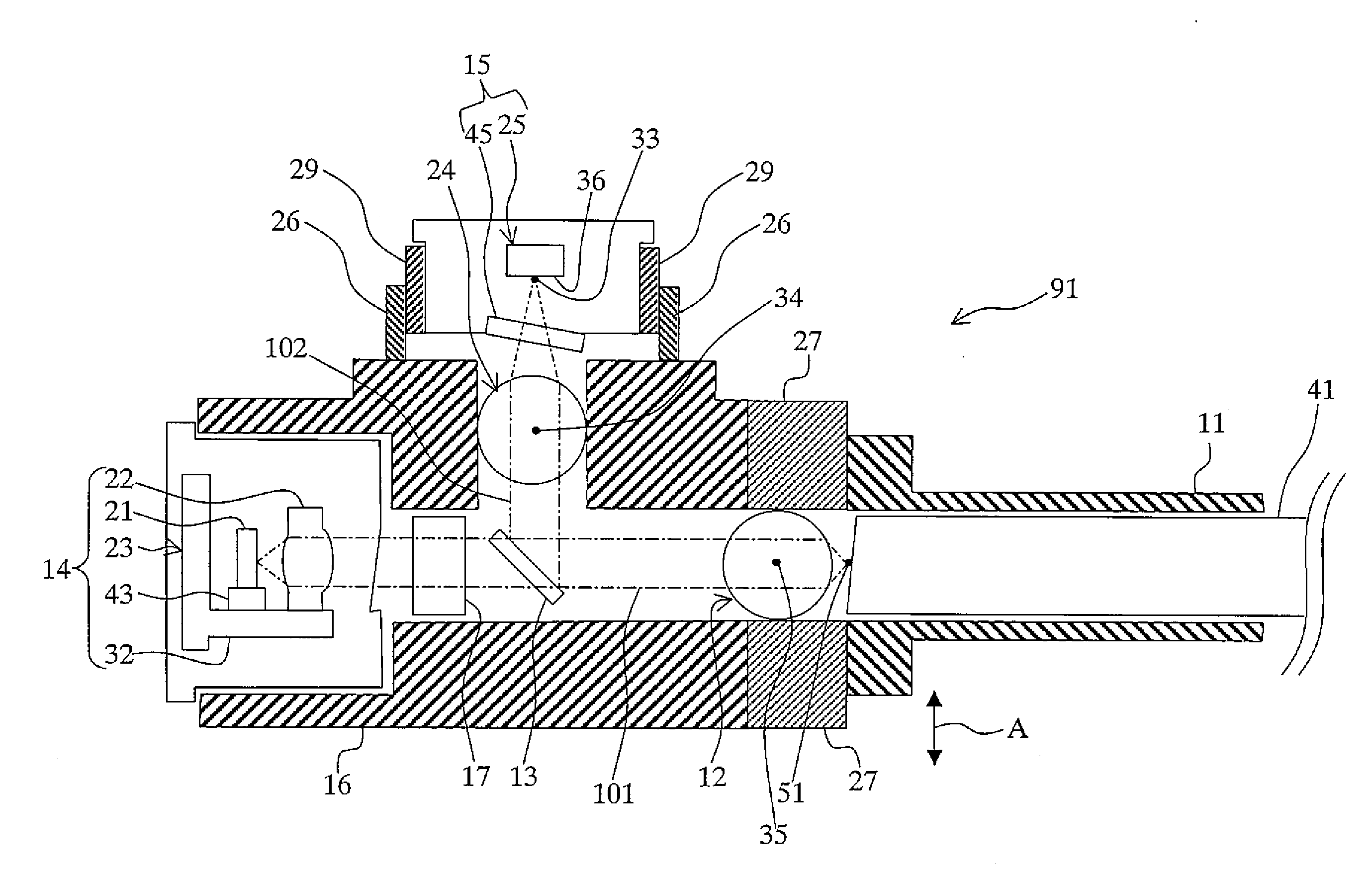
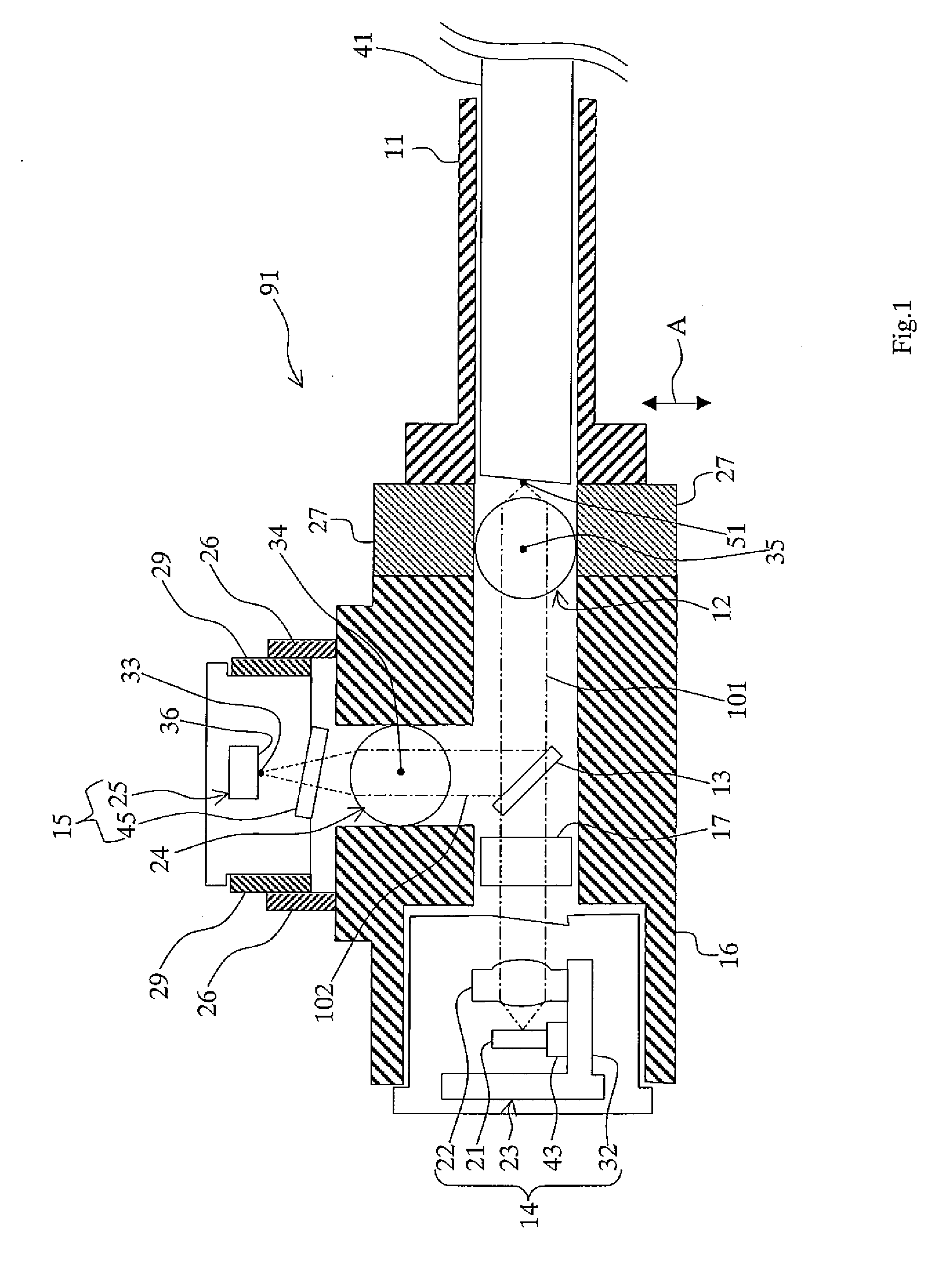
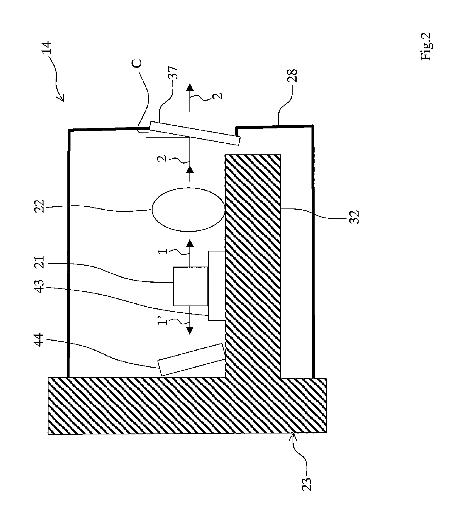
[0031]FIG. 1 is a schematic view showing an example of a single-fiber two-way optical communication module according to the embodiment. A single-fiber two-way optical communication module 91 shown in FIG. 1 has: at least one light emitting module 14 including a light emitting device 21 for emitting light, a light-emission-side lens 22 for refracting outgoing light emitted from the light emitting device 21 to parallel rays, a heat sink 43 having the light emitting device 21 thereon, for dissipating heat from the light emitting device 21, a column-shaped holding part 32 extending in the direction parallel with the light outgoing direction of the light emitting device 21, and a stem 23 for holding the light-emission-si...


PUM


Abstract

A light emitting module according to the present invention is characterized in that a light emitting device and a light-emission-side lens are held close to each other by a holding part extended from part of a stem in parallel with outgoing light of the light emitting device, and light emitted from the light emitting device is refracted. A single-fiber two-way optical communication module according to the present invention has the light emitting module and, in addition, collimate lenses close to an optical fiber and a light receiving device, and is characterized in that splitting of light to a light receiving module or coupling of light from the light emitting module is performed with parallel rays. Each of the collimate lenses condenses the parallel rays to an incident / outgoing end face of the optical fiber, condenses the parallel rays to a light receiving face of the light receiving device, and outputs, as parallel rays, outgoing light from the light emitting module.

Description

[0001] The present application is based on, and claims priority from, J.P. Application 2005-172479, filed Jun. 13, 2005, the disclosure of which is hereby incorporated by reference herein in its entity. BACKGROUND OF THE INVENTION [0002] 1. Field of the Invention [0003] The present invention relates to a light emitting module realizing improved light coupling efficiency and a single-fiber two-way optical communication module having the light emitting module and used for two-way optical communication of a plurality of waves performed by a single fiber. [0004] 2. Description of the Related Art [0005] Hitherto, in an optical fiber communication system, a two-way optical communication module is used for an access network system of telephone communication or the like (refer to, for example, Japanese Patent Application National Publication Laid-open No. 2003-524789). [0006] In an optical communication module disclosed in Japanese Patent Application National Publication Laid-open No. 2003-...

Claims


Application Information

Patent Timeline
Patent Type & Authority Applications(United States)
IPC IPC(8): G02B6/36G02B6/32
CPCG02B6/4246
Inventor NISHIZAWA, TOSHIKIMITSUHASHI, YUJIUCHIDA, TOSHIAKI
Owner NTT ELECTORNICS CORP
Why Eureka
Try Eureka