High efficiency optical coupler

a high-efficiency, optical coupler technology, applied in the direction of instruments, lighting and heating apparatus, fibre light guides, etc., can solve the problem of source diminishing the light coupling efficiency, and achieve the effect of reducing system aberration, reducing light path leakage, and large variability

Active Publication Date: 2010-09-23
VENTURA MFG1 LLC
View PDF11 Cites 17 Cited by
  • Summary
  • Abstract
  • Description
  • Claims
  • Application Information

AI Technical Summary

Benefits of technology

[0005]In all embodiments the light source is placed at or near the vertex of the second conic reflector. The second conic reflector operates at the maximum system aperture by receiving a plane wave from the first conic reflector. This creates the advantage that the light source and any associated mounting hardware blocks or absorbs the least amount of reflected light from the first conic reflector, thus improving efficiency. Any other location for the light source diminishes the light coupling efficiency.
[0006]The function of the second conic reflector is to converge the reflected light onto a focal plane with the desire to set the focal plane past the vertex of the first conic reflector. This is achieved at least in part by adjusting the radius and conic constant of the second conic reflector. It becomes apparent that the best location for the negative element is at the vertex of the first conic mirror. This is where the N.A. of the converging light can be changed before its arrival at the focal plane. There is a range for the diameter of the negative element between a large diameter that will block or divert a large amount of emitted light and a small diameter at which the effectiveness of the negative element will diminish. The negative element will push out the location of the focal plane thus making the light more usable for the next stage of optical tasking.
[0007]In a first embodiment, the first conic reflector is parabolic and the light source is located at the focus of the first conic reflector. The light from the source is reflected off the first conic reflector, is collimated and transfers to the second conic reflector. Light reflected from the second conic reflector enters the negative element before reaching its focal plane, thereby reducing the converging ray angle in order to obtain the desired N.A. By optimizing the curves of the second conic reflector in relationship to the negative element, more light can be captured and manipulated to perform a specified function (such as coupling into a fiber optic), thus achieving the desired N.A which increases the efficiency of the optical coupler system.
[0010]In a fourth embodiment, the first conic reflector and the second conic reflector join at a common edge with a minimal amount of seam exposure thus eliminating any light path leakage. The optical coupler reduces aberrations in the system by allowing either the second conic reflector or the third negative element a large variability based on the desired application. The conic required at the second conic reflector and the negative optical element are task specific, e.g., coupling into a fiber optic requires different reflective functions than the creation of collimated light.
[0011]The improved optical coupler can be configured for a variety of optical functions such as shaping light, fiber optic coupling, creating collimated or near collimated light, or any unique illumination purpose. Such a system works well for hemispherical radiators like LEDs but can accommodate filaments and arcs sources as well. The present invention reforms a high N.A. source light (for example, N.A.>0.9) to a lower N.A. source light (for example, 0.55 or less), thus allowing the use of conventional optics in the post focal plane optical path with very little loss of light.

Problems solved by technology

Any other location for the light source diminishes the light coupling efficiency.

Method used


Image

  • High efficiency optical coupler
  • High efficiency optical coupler
  • High efficiency optical coupler

Examples


Embodiment Construction

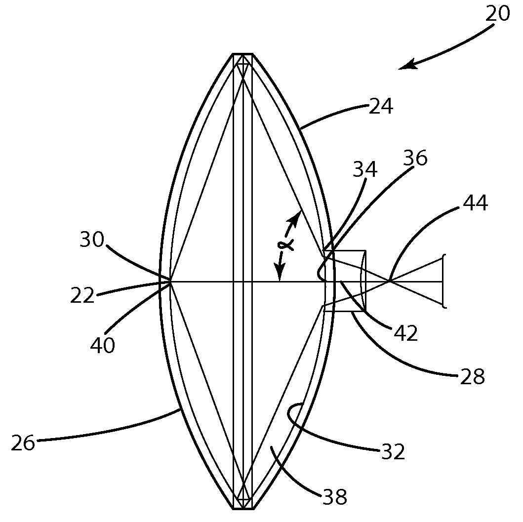
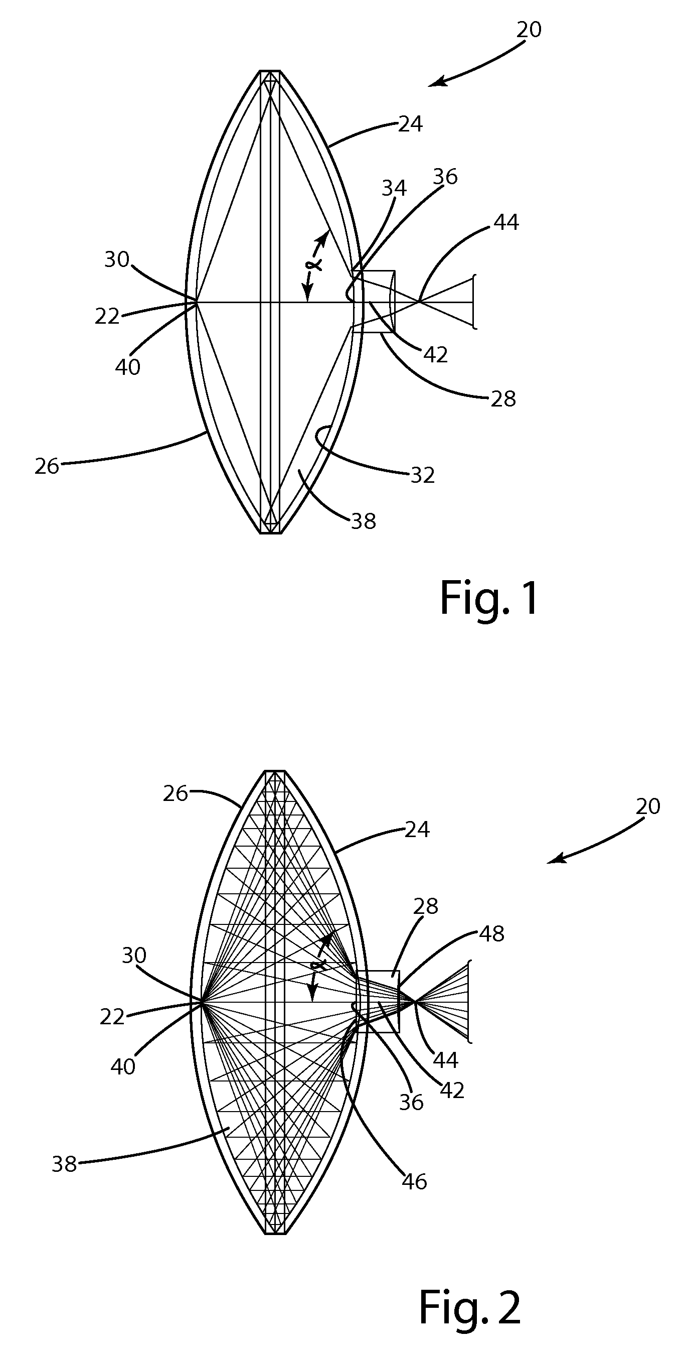
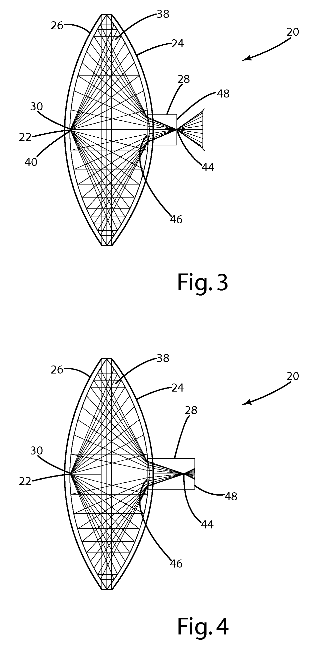
[0023]A high efficiency optical coupler in accordance with an embodiment of the invention is illustrated in FIG. 1 and generally designated 20. The high efficiency optical coupler 20 includes a light source 22, first reflector 24, second reflector 26, and negative element 28. The light source 22 is located generally at the vertex 30 of the second reflector 26 and transmits a light output or optical radiation over a solid angle of almost 2 Pi steradians (an NA of 0.95) onto the interior surface 32 of the first reflector 24. The interior surface 32 of the first reflector 24 reflects the light from the light source 22, thus changing the path of light emitted by the light source 22. The first reflector 24 is a conic and has an additional function of collimating the light from the light source 22, thus transferring a plane wave to the second reflector 26. Light is then reflected off the second reflector 26 toward the negative element 28 aligned with an aperture 34 at the vertex 36 of the...


PUM


Abstract

An optical coupling device enabling spherical or hemispherical light sources to be more fully utilized by gathering more of the emitted radiation and reducing the angle of emission. The optical coupling device includes a first conic reflector having an aperture at the first conic reflector vertex; a second conic reflector coaxial with the first conic reflector and opening toward the first conic reflector; a light source positioned at the second conic reflector vertex; and a negative element located at the aperture for reducing the numerical aperture of the light emitted from the optical coupling device. The optical coupling device may include a refractive medium between the first and second conic reflectors. The present invention provides for improved efficiencies when transferring or coupling optical energy into additional optical systems, and may be used with solid state light as well as conventional sources.

Description

BACKGROUND OF THE INVENTION[0001]The present invention relates to the collection of light from a high numerical aperture (N.A.) source and reforming the light into a lower N.A. point source for coupling into an optical system.[0002]Most modern illumination sources, such as bulbs, light emitting diodes and arc lamps are extended sources that radiate light in a spherical or hemispherical pattern. Standard refractive optics can transmit or focus a portion of the source light but at a substantial loss, typically greater than 70%. Standard reflective optics possess better efficiencies but essentially still lose 50% of the total light. With the ever increasing cost of energy, it will be important to generate and utilize light as efficiently as possible. To that end, light will preferably be shaped, controlled and otherwise manipulated, and then placed within the desired area and function with as little loss as possible. Such conditions call for the use of light coupling technologies. Exem...

Claims


Application Information

Patent Timeline
Patent Type & Authority Applications(United States)
IPC IPC(8): G02B6/26
CPCG02B6/0006G02B6/4206G02B17/0605G02B17/008G02B17/004
Inventor BOURGET, PAUL L.
Owner VENTURA MFG1 LLC
Why Eureka
Try Eureka