Bi-directional transceiver module based on silicon optic bench

a transceiver module and optical bench technology, applied in the direction of optics, optical waveguide light guides, instruments, etc., can solve the problems of low external quantum efficiency, low efficiency of high-speed transmission, complicated fabrication process, etc., to improve the light coupling efficiency of optical signals, reduce the difficulty, time and cost of fabrication, and improve the effect of optical signal emitted

Inactive Publication Date: 2006-03-14
FOCI FIBER OPTIC COMM
View PDF10 Cites 17 Cited by
  • Summary
  • Abstract
  • Description
  • Claims
  • Application Information

AI Technical Summary

Benefits of technology

[0009]The present invention is a light coupling and alignment design based on a silicon optical bench. By combining the optical characteristics of each optical element and SiOB production technology, the present invention provides a bi-directional transceiver module that is capable of processing multiple wavelengths. The first object of the present invention is to provide a bi-directional transceiver module based on a silicon optical bench, comprising at least a laser diode, at least a signal detector, at least a thin film filter, at least an optical lens, a groove, an optical fiber, and a silicon optical bench. The present invention utilizes a silicon wafer us a substrate, and utilizes an optical fiber and grooves etched by semiconductor etching process for guiding light. The present invention does not utilize the planar light circuit fabrication process to achieve the planar light guiding. The thin film filter can selectively reflect the optical signals of a specific wavelength to the other direction, and let the rest pass. By adjusting the reflection angle, the optical signals can be reflected to a specific location. Therefore, the thin film filter can separate optical signals of different wavelengths, and the present invention can be used as a WDM. The thin film filter must be placed between the laser diode or the signal detector and the optical fiber. The optical lens and the optical fiber can be combined to improve the light coupling efficiency of the optical signal emitted from the laser diode on its transmission path. The optical lens must be placed between die laser diode and the optical fiber. The signal detector is for receiving, the optical signal of different wavelength transmitted from the other end.
[0010]The present invention has the functions of both an optical transmitter and an optical receiver, and uses only a single optical fiber to transmit optical signals. Therefore, the present invention is a bi-directional module. As the entire module is fabricated on a silicon wafer, and the grooves etched by semiconductor etching process is highly precise, the bi-directional transceiver module based on an SiOB can utilize a passive alignment packaging to reduce the difficulty, time, cost of fabrication as well as achieve small size and small optical loss. The present invention is suitable for high-speed transmission.

Problems solved by technology

Most packaging arrangements are typically assembled in a metal can in that the fabrication process is complicated and expensive. FIG. 1 of the attached drawings shows the structure of a conventional bi-directional transceiver using the “TO-can”.
For example, it is an active alignment packaging method that is time-consuming, and the external quantum efficiency may be low due to the high light coupling loss between laser diode and optical fiber.
Therefore, TO-can is suitable for low-speed transmission, but not for high-speed transmission.
However, as the structure uses only wave guide 203 for wavelength division, its ability in signal division is poor.
In addition, as the coupling between laser diode 201 and wave guide 203 is difficult, both the optical loss and the fabrication cost are high.
But, as the coupling loss between laser diode 201 and wave guide 203 is too large, the overall loss of this improved structure is still high.
In addition, the special thin film filter is expensive, and the overall fabrication process is complicated.
However, the alignment design of a silicon optical bench affects the transmission path and the loss rate of the light.
During the transmission, the mode of the optical field changes after the light passing optical elements; hence, the optical loss occurs.

Method used


Image

  • Bi-directional transceiver module based on silicon optic bench
  • Bi-directional transceiver module based on silicon optic bench
  • Bi-directional transceiver module based on silicon optic bench

Examples


first embodiment

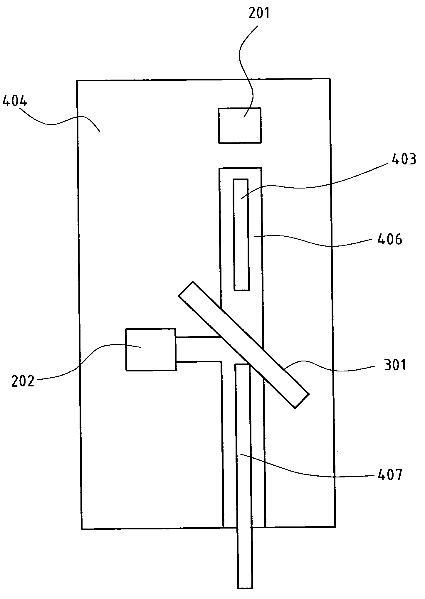
[0024]FIG. 4 shows the present invention, comprising a laser diode 201, a signal detector 202, a thin film filter 301, an optical lens 403, a groove 406, an optical fiber 407, and a silicon optical bench 404. Optical lens 403 is placed between laser diode 201 and thin film filter 301 for improving the coupling efficiency of the optical signal emitted from laser diode 201 to optical fiber 407. Thin film filter 301 is placed between optical lens 403, signal detector 202 and optical fiber 407 for reflecting the optical signal transmitted from optical fiber 407 to signal detector 202. All the optical elements are integrated on silicon optical bench 404, and utilize only a single optical fiber 407 for optical signal transmission.

[0025]FIG. 5 shows the optical transmitter of FIG. 4. The optical transmitter comprises a laser diode 201, a thin film filter 301, an optical lens 403, and an optical fiber 407. Output optical signal 505 is emitted from laser diode 201, entering optical lens 403,...

second embodiment

[0033]FIG. 11 shows the present invention, a bi-directional transceiver module capable of processing multiple wavelengths. Two laser diodes 2011, 2012, and thin film filter 3013 are placed on a rectangular SiOB 4041. The two diodes 2011, 2012 can emit two optical signals of different wavelengths. Groove 4061 and optical fiber 407 are utilized for guiding and transmitting optical signals. Three signal detectors 2021, 2022, 2023 and corresponding thin film filters 3011, 3012 and 3014 are utilized for receiving optical signals of three different wavelengths. The entire transceiver module utilizes five optical lenses 4031–4035 to adjust the mode of the optical field to improve coupling efficiency. This embodiment is able to transmit two optical signals and receive three optical signals, all of different wavelengths.

third embodiment

[0034]FIG. 12 shows the present invention. By varying groove 4062, this embodiment uses a square SiOB 4042 to meet a different application requirement. In this embodiment, a laser diode 2013 emits an optical signal, groove 4062 and optical fiber 407 are for guiding and transmitting optical signals, four signal detectors 2024–2027 with corresponding thin film filters 3015–3018 are for receiving four optical signals simultaneously, and two optical lenses 4036, 4037 are used to adjust the mode of the optical field and reduce coupling loss.

[0035]Therefore, the present invention is applicable and can be extended to place a plurality of optical transmitters and a plurality of optical receivers on a silicon optical bench. By utilizing a plurality of thin film filters of various optical characteristics, such as reflection angle, the present invention can act as a multiple wavelengths, bi-directional transceiver module with a single optical fiber. In addition, a plurality of optical lenses c...


PUM


Abstract

A bi-directional transceiver, integrated module based on a silicon optical bench is provided, which comprises at least a laser diode, at least a signal detector, at least a thin film filter, at least an optical lens, an optical fiber and an SiOB. As the optical signal of specific wavelength can be reflected or inserted by thin film filter, the module has functions of a wavelength division multiplexer and a bi-direction transceiver. Furthermore, the optical lens improves the coupling efficiency between the laser diode and the optical fiber. On the other hand, a plurality of optical elements are integrated on the same SiOB. Hence, only a single optical fiber is used and optical signals of multiple wavelengths can be handled simultaneously.

Description

FIELD OF THE INVENTION[0001]The present invention relates to the bi-directional optic transceiver module and, more particularly to a bi-directional transceiver module based on a silicon optical bench (SiOB).BACKGROUND OF THE INVENTION[0002]Conventional bi-directional transceiver modules with 1550 / 1310 nm wavelength are utilized in a communication terminal system, such as the broad-band network and the optical fiber cable TV system. An optical transmitter converts an electric signal to an optical signal for transmission, whereas an optical receiver converts the received optical signal to an electric signal. The optical transmitter module connects the modulated light or signal emitted from the front section of a laser diode to an optical fiber. The light transmitted along the optical fiber is converted back to electrical signal at the other end of the optical receiver module.[0003]In general, the optical transmitter and receiver are integrated in a single packaging arrangement module,...

Claims


Application Information

Patent Timeline
Patent Type & Authority Patents(United States)
IPC IPC(8): G02B6/12G02B6/34G02B6/42
CPCG02B6/29362G02B6/2938G02B6/4246G02B6/4214G02B6/423G02B6/4206
Inventor LIN, SONG-FUREWANG, PIN-SUNGCHIU, CHIEN-HSIUNGLIU, LI-JEN
Owner FOCI FIBER OPTIC COMM
Why Eureka
Try Eureka