System and method utilizing guided fluorescence for high intensity applications

a fluorescence and high intensity technology, applied in the field of high brightness optical sources, can solve the problems of limited ability to increase insufficient brightness of most types of optical sources to deliver the intensity or fluence necessary, and insufficient time for heat produced by absorption in the targeted tissue to conduct away from the absorption volume of the targeted tissu

Inactive Publication Date: 2006-12-14
CUTERA
View PDF22 Cites 63 Cited by
  • Summary
  • Abstract
  • Description
  • Claims
  • Application Information

AI Technical Summary

Problems solved by technology

This brightness constraint limits the ability to increase the intensity or fluence by simply focusing an optical beam.
Most types of optical sources have insufficient brightness to deliver the intensity or fluence necessary to perform typical aesthetic medical procedures, such as removal of hair, pigmented lesions, or superficial small blood vessels.
That is, the optical energy needs to be applied in a sufficiently short pulse, so that the heat produced by absorption in the targeted chromophore has insufficient time to conduct away from the absorption volume of the targeted tissue.
The heat thus locally raises the chromophore temperature, denaturing, or damaging, the tissue immediately surrounding the chromophore.
The non-targeted areas are left undamaged or only slightly damaged by the procedure.
Specifically, known commercial laser therapy systems have often employed large, rather expensive lasers to generate sufficient intensity or fluence for therapeutic efficacy.
The lasers typically require precise mechanical tolerances and thus cannot readily be serviced.
Additionally, existing lasers are often inflexible in the light wavelengths they produce.
Finally, laser-based therapies are accompanied by a significant eye safety risk.
Eye safety is particularly problematic when there are multiple laser wavelengths and pulse parameters used at a medical site and where multiple spectacle styles and optical characteristics for protective eyewear are required.
While these alternative structures can have significant cost advantages over optically-pumped lasers, each has significant disadvantages.
When sufficient laser diodes are combined to generate therapeutic light fluences, the total cost of the device is quite high, often in the many thousands of dollars.
Moreover, high power laser diodes are only available in a limited number of wavelengths; they are not currently available in wavelengths shorter than approximately 630 nm and thus cannot target the hemoglobin absorption peak near 550 nm.
While flashlamps are very low in cost, they have a large emitting volume and low spectral brightness.
The reflectors must be precisely built and calibrated, as errors can produce hot spots in the spatial energy distribution.
Furthermore, as the spectrum of light energy generated by lamps is quite broad and much of the total light energy may disadvantageously cause heating of non-target chromophores.
However, the filter is expensive, reduces the fluence of the desired light, and only imperfectly removes the unwanted light.
Both direct flashlamp and filtered flashlamp systems produce light of only moderate spectral brightness over a relatively large area and thus cannot produce a spatially localized, high spectral fluence source.
Unfortunately, LEDs typically have insufficient brightness to cause selective photothermolysis of appropriate tissues or structures bearing naturally-occurring (endogenous) chromophores.

Method used


Image

  • System and method utilizing guided fluorescence for high intensity applications
  • System and method utilizing guided fluorescence for high intensity applications
  • System and method utilizing guided fluorescence for high intensity applications

Examples


Embodiment Construction

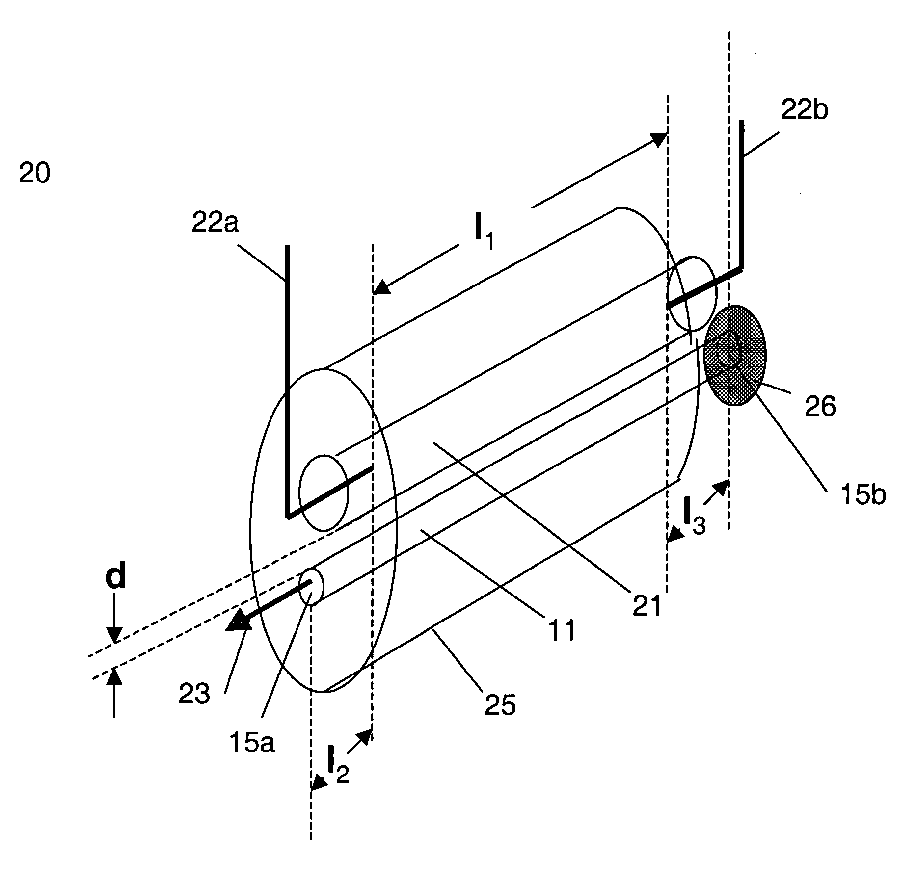
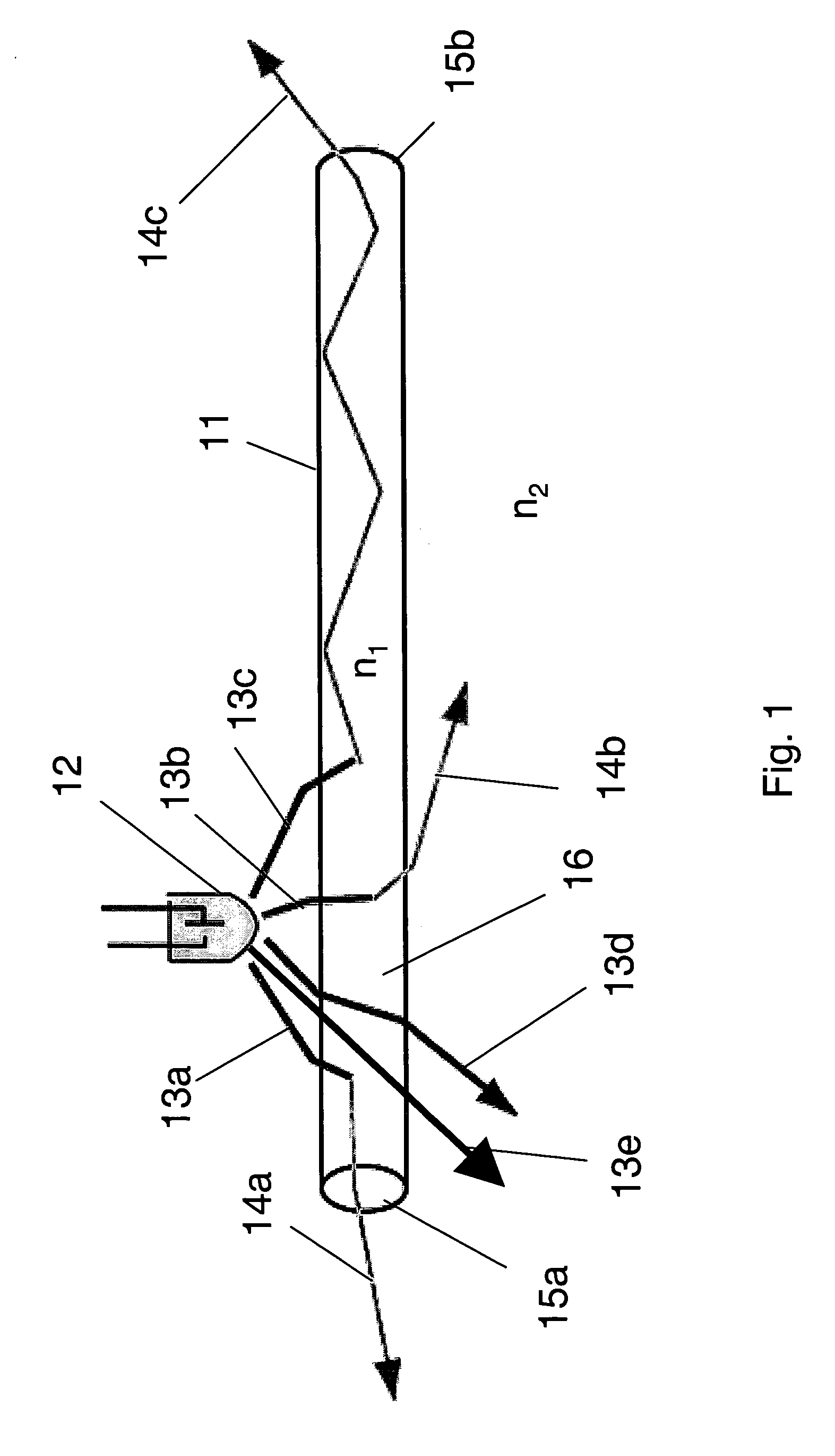
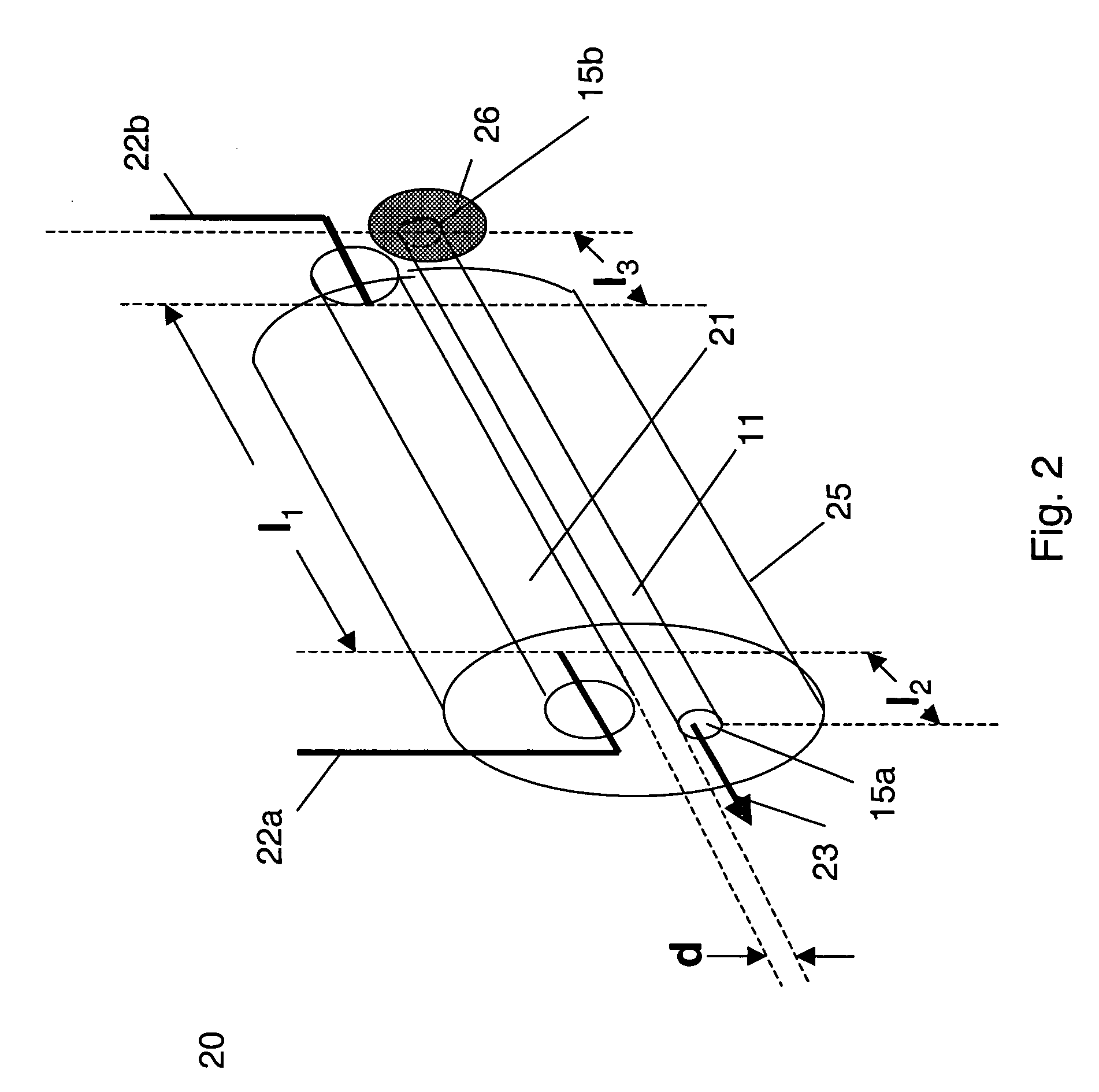
[0031] One embodiment herein provides a fluorescence concentrator which is capable of producing a high spectral brightness and high intensity optical source suitable for providing therapeutic energy, which can be used for medical procedures.

[0032] An embodiment herein provides a system which includes a body with a fluorophore, which can be a transparent optical material doped with a fluorophore to form a fluorescence concentrator. The fluorescent concentrator can be optically smooth at most or all surface boundaries. In one embodiment the material has an index of refraction higher than its surroundings so that total internal reflection (TIR) can occur at the concentrator surfaces. The concentrator has at least one surface for outputting energy. This output area can be significantly smaller than the total surface area of the fluorescence concentrator. The concentrator is illuminated by an adjacent illumination source which optically pumps the fluorophore causing it to emit fluoresce...


PUM


Abstract

A fluorescence concentrator system that provides for high brightness light source. The system can include a host doped with fluorescent material, which is optically pumped by an adjacent illumination source. The fluorescence concentrator captures a portion of the isotropically emitted fluorescent light and guides it to an output surface. The fluorescent energy emerging the output surface provides a high brightness light source suitable for a number of applications. For example, the fluorescence concentrator system can be used as the light source in a medical apparatus suitable for various aesthetic procedures. Further aspects of the fluorescent concentrator system can include providing for controlling the illumination source to output pumping energy suitable for high energy applications.

Description

RELATED APPLICATIONS [0001] This application is a continuation of U.S. patent application Ser. No. 10 / 897,352, filed Jul. 22, 2004. This application claims priority from U.S. Provisional Patent Applications Ser. Nos. 60 / 493,171, filed Aug. 7, 2003, and 60 / 582,489 filed Jun. 24, 2004, both of which are incorporated herein by reference.BACKGROUND OF THE INVENTION [0002] The invention relates generally to the generation of a high brightness optical source through use of a fluorescence concentrator system. The source can be used in a variety of applications, including various medical aesthetic procedures. [0003] As an aid in demonstrating the utility of the invention, it is helpful to review some basic optical concepts. For a pulsed optical source the pulse energy is defined as the average optical power during the pulse multiplied by the pulse width. Typical units for pulse energy are Joules, for power are Watts, and for time is seconds. The optical intensity is the power per unit area,...

Claims


Application Information

Patent Timeline
Patent Type & Authority Applications(United States)
IPC IPC(8): A61N5/06A61B18/20F21K99/00G02B6/42
CPCA61B18/203G02B6/4298A61B2018/00452G02B6/0003
Inventor NIGHTINGALE, JOHN L.SPOONER, GREGORY J.GOLLNICK, DAVID A.MACFARLAND, DEAN A.
Owner CUTERA
Why Eureka
Try Eureka