[0012] According to the present invention, techniques related to
solar energy are provided. In particular, the present invention provides a method and resulting device fabricated from a plurality of photovoltaic regions provided within one or more substrate members. More particularly, the present invention provides a method and resulting device for manufacturing the photovoltaic regions within the substrate member, which is coupled to a plurality of concentrating elements. Merely by way of example, the invention has been applied to solar panels, commonly termed modules, but it would be recognized that the invention has a much broader range of applicability.
[0018] In a specific embodiment, the present invention provides an alternative solar
cell device. The device has a first substrate member and a plurality of photovoltaic strips overlying the first substrate member. The device has an encapsulant material overlying a portion of the first substrate member. The device has a first
refractive index characterizing the encapsulant material, and has a second substrate member comprising a plurality of optical concentrating elements thereon. In a preferred embodiment, the second substrate member is overlying the plurality of photovoltaic strips such that at least one of the optical concentrating elements is operably coupled to at least one of the one of the plurality of photovoltaic strips. Preferably, the plurality of concentrating elements is composed by at least a second substrate material. The device has a second
refractive index characterizing the second substrate material. The second
refractive index is substantially matched to the first refractive index to cause one or more photons to
traverse through at least one of the optical concentrating elements through a portion of the encapsulant and to a portion of one of the photovoltaic strips to reduce an amount of internal reflection from a portion of the one concentrating element. In a specific embodiment, the reduced amount of internal reflection causes an increase of a quantity of photons reaching a photovoltaic region.
[0019] In yet an alternative embodiment, the present invention provides a solar
cell device with improved encapsulant material. The device has a first substrate member and a plurality of photovoltaic strips overlying the first substrate member. The device has an encapsulant material overlying a portion of the first substrate member. The device has a first refractive index characterizing the encapsulant material, and has a second substrate member comprising a plurality of optical concentrating elements thereon. In a preferred embodiment, the second substrate member is overlying the plurality of photovoltaic strips such that at least one of the optical concentrating elements is operably coupled to at least one of the one of the plurality of photovoltaic strips. Preferably, the plurality of concentrating elements is composed by at least a second substrate material. The device has a second refractive index characterizing the second substrate material. The first refractive index of the encapsulant material is substantially matched with the second refractive index to facilitate a transfer of one or more photons from at least one of the optical concentrating elements to a portion of one of the photovoltaic strips in a preferred embodiment.
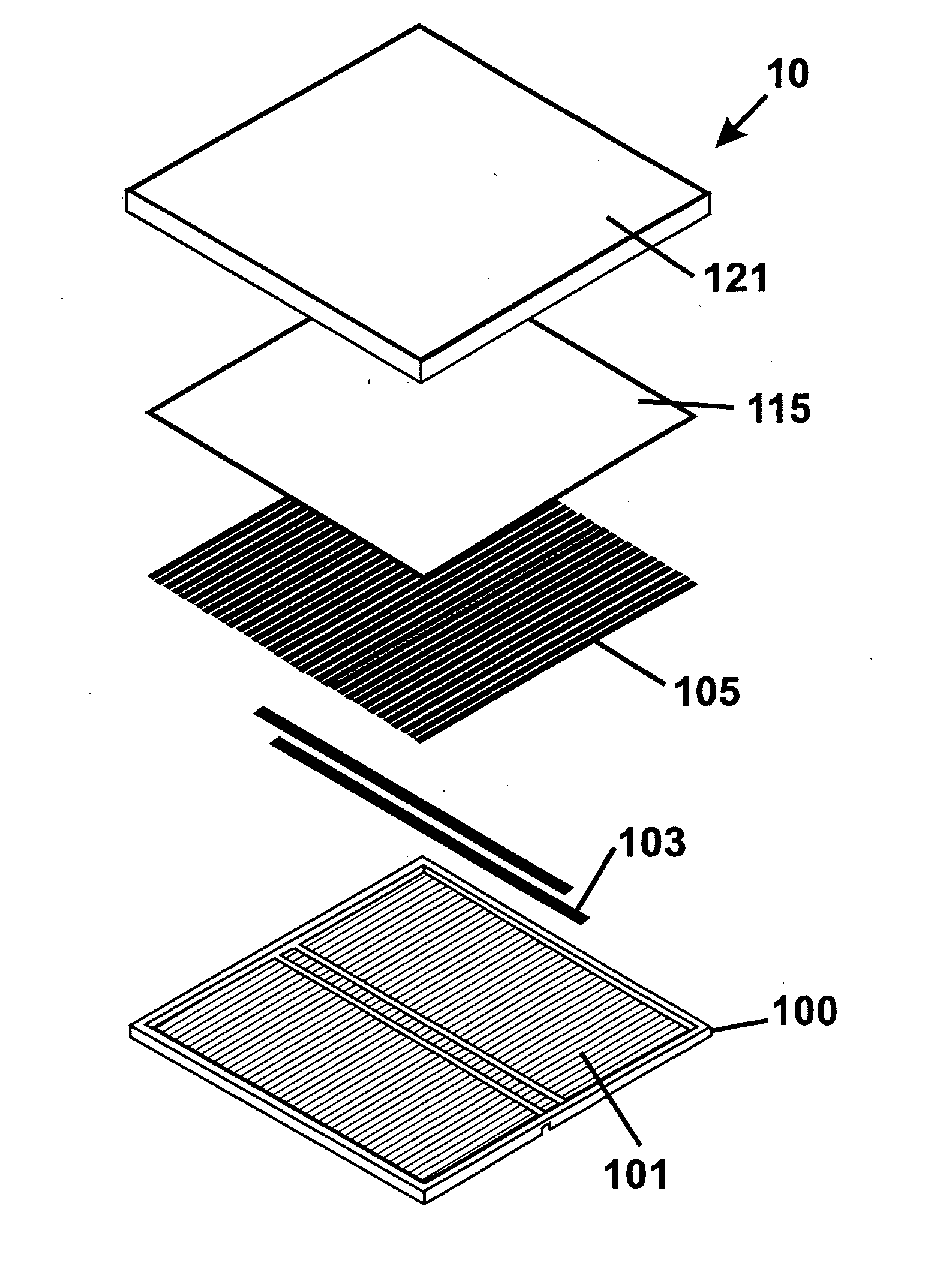
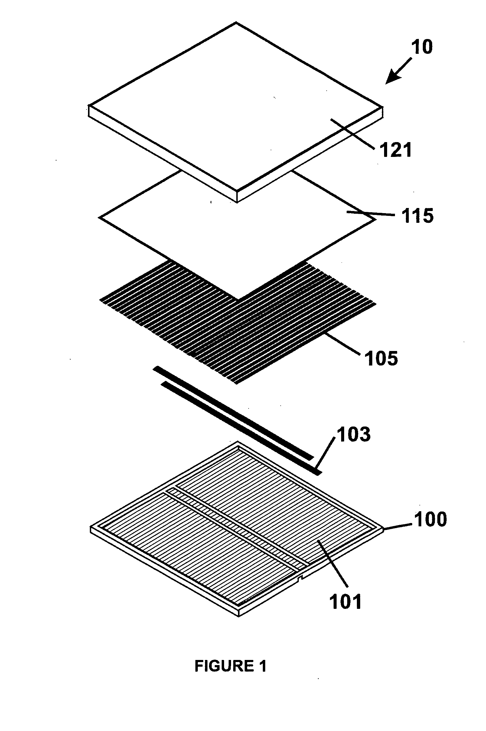
[0020] In yet an alternative embodiment, the present invention provides a packaged solar
cell assembly being capable of stand-alone operation to generate power using the packaged solar
cell assembly and / or with other solar cell assemblies. The packaged solar
cell assembly includes rigid front cover member having a front cover surface area and a plurality of concentrating elements thereon. Each of the concentrating elements has a length extending from a first portion of the front cover surface area to a second portion of the front cover surface area. Each of the concentrating elements has a width provided between the first portion and the second portion. Each of the concentrating elements having a first
edge region coupled to a first side of the width and a second
edge region provided on a second side of the width. The first
edge region and the second edge region extend from the first portion of the front cover surface area to a second portion of the front cover surface area. The plurality of concentrating elements is configured in a parallel manner extending from the first portion to the second portion. In addition, the packaged solar
cell assembly includes a plurality of photovoltaic strips arranged respectively on the plurality of concentrating elements. Each of the plurality of photovoltaic strips has a strip width and a strip length. Each of the photovoltaic strips
coupling at least one of the plurality of concentrating elements. The packaged solar cell
assembly additionally includes a
coupling material provided between each of the photovoltaic strips and each of the concentrating elements to optical couple the photovoltaic strip to the concentrating element. The packaged solar cell
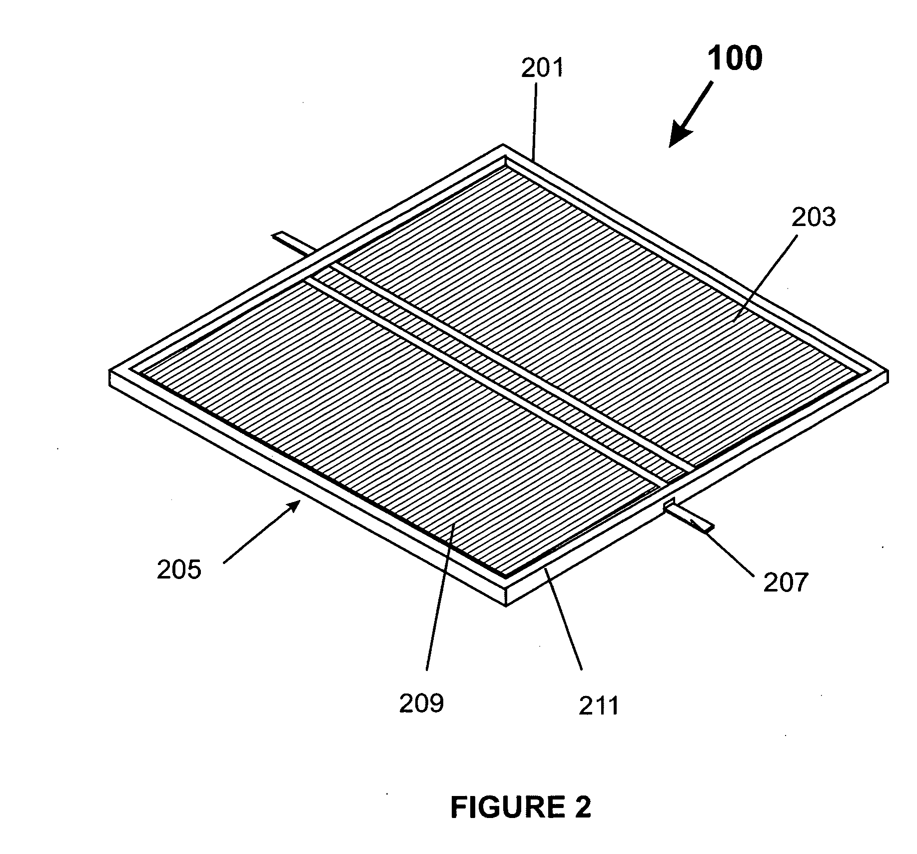
assembly further includes a rigid back cover member. The back cover member has a plurality of support regions. The plurality of support regions provides respectively mechanical support to respective plurality of photovoltaic strips. In addition, the
package solar cell assembly includes a sealed region to mechanically couple the rigid back cover member to the rigid front cover member to provide a sealed sandwiched assembly capable of maintaining the plurality of photovoltaic strips substantially free from
moisture. The sealed sandwiched assembly can be handled while maintaining the plurality of photovoltaic strips substantially free from mechanical damage.
[0023] Many benefits are achieved by way of the present invention over conventional techniques. For example, the present technique provides an easy to use process that relies upon conventional technology such as
silicon materials, although other materials can also be used. Additionally, the method provides a process that is compatible with conventional process technology without substantial modifications to conventional equipment and processes. Preferably, the invention provides for an improved solar cell, which is less costly and easy to
handle. Such solar cell uses a plurality of photovoltaic regions, which are sealed within one or more substrate structures according to a preferred embodiment. In a preferred embodiment, the invention provides a method and completed solar
cell structure using a plurality of photovoltaic strips free and clear from a module or panel assembly, which are provided during a later assembly process. Also in a preferred embodiment, one or more of the solar cells have less
silicon per area (e.g., 80% or less, 50% or less) than conventional solar cells. In preferred embodiments, the
present method and cell structures are also light weight and not detrimental to building structures and the like. That is, the weight is about the same or slightly more than conventional solar cells at a module level according to a specific embodiment. In a preferred embodiment, the present solar cell using the plurality of photovoltaic strips can be used as a “drop in” replacement of conventional solar cell structures. As a drop in replacement, the present solar cell can be used with conventional solar cell technologies for efficient implementation according to a preferred embodiment. Depending upon the embodiment, one or more of these benefits may be achieved. These and other benefits will be described in more detail throughout the present specification and more particularly below.

