Optical multilayer thin-film system

a thin-film system and optical multi-layer technology, applied in the field of thin-film systems, can solve the problems of poor monochromatic performance, large light loss, and inability to adjust the cut-off wavelength sub>c /sub>, and achieve the effect of increasing spectral reliability and uniform color distribution

Inactive Publication Date: 2006-12-21
ASIA OPTICAL CO INC
View PDF3 Cites 17 Cited by
  • Summary
  • Abstract
  • Description
  • Claims
  • Application Information

AI Technical Summary

Benefits of technology

[0018] The present invention employs a plurality of high and low refractive index layers alternately laminated with each other. Each high refractive index layer is designed to have an optical thickness larger than that of the low refractive index layer. This significantly increases spectral reliability of the present multilayer thin-film system independent of the variation of incident light angle, and thus uniformity of color distribution.

Problems solved by technology

The absorption filter has the disadvantages of poor monochromatic performance and large light loss.
The disadvantages of an absorption cut-off filter are that the cut-off wavelength λc is not adjustable and the steepness of the cut-off slope is not sufficient.
These make the absorption cut-off filter impractical in application.
However, the cut-off wavelength λc of the interference filter is very sensitive to the incident angle of the light as the light enters the filter.
Such a spectral shift tends to vary the color being displayed, and thus adversely affects the optical performance of the optical filter with the above multilayer thin-film system disposed thereon.
These designed layer thickness fluctuations significantly reduce performance degradation caused by undesired minor thickness deviations resulting from the thickness fluctuation during coating process in conventional filters, and further ease difficulties in producing such a super-narrow band-pass filter.
However, such a random multiplayer thin-film system is rather complex in design, which requires three layers of materials of different refractive indexes and more than sixty layers to be laminated.
In addition, similar to the conventional filter film design, this random multiplayer thin-film system still encounters shifts of the transmittance peak.
However, the above-mentioned random multiplayer thin-film systems for filters still cannot address the problem of spectral shifts with variations of incident angle, and thus are not suitable for being employed as the film system for an interference cut-off filter.

Method used


Image

  • Optical multilayer thin-film system
  • Optical multilayer thin-film system
  • Optical multilayer thin-film system

Examples


Embodiment Construction

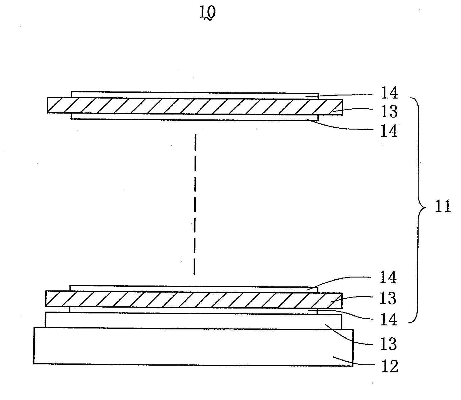
[0023] In the preferred embodiment of the present invention as discussed below, an interference cut-off filter is taken as an example to introduce the present multilayer thin-film system. However, it is apparent to those having ordinary skills in the art that the present invention is also applicable to multilayer thin-film system of other optical elements, such as lenses.

[0024] Referring to FIG. 3, a multilayer thin-film system 11 in accordance with the present invention, which is use for an optical element, such as the interference cut-off filter 10, comprises a substrate 12 (BK-7), a plurality of layers 13 formed of high refractive index material, such as TiO2, and a plurality of layers 14 formed of low refractive index material, such as SiO2. The high and low refractive index layers 13, 14 are alternately laminated on the substrate 12, and are designed to have different optical thickness. The optical thickness is defined as the physical thickness “d” of the layer multiplied by t...


PUM


Abstract

An optical multilayer thin-film system (11) includes a number of high refractive index layers (13), and a number of low refractive index layers (14) alternately laminated with the high refractive index layers. Each high refractive index layer has an optical thickness larger than that of each low refractive index layer. When such a multilayer thin-film system is applied to an optical element, spectral shift with respect to variation of the incident light angle is significantly reduced.

Description

BACKGROUND OF THE INVENTION [0001] 1. Field of the Invention [0002] The present invention relates to a thin-film system, and in particular to a multilayer thin-film system for use with an optical element, such as an optical filter and lens. [0003] 2. Description of Prior Art [0004] Optical film coatings have been widely applied to lenses or optical filters in projectors, traditional cameras, digital cameras, mobile phones and astronomical telescopes to achieve various optical functions. These optical functions include UV absorption, anti-reflection, color filtering, IR cutting, and so on. Thereinafter, the optical filter will be taken as an example to introduce the thin-film system of optical film coating and corresponding optical functions achieved. The so-called optical filter is a device that is designed according to the light absorption and interference theory, and selectively transmits light having certain properties (often, a particular range of wavelengths, namely colors of l...

Claims


Application Information

Patent Timeline
Patent Type & Authority Applications(United States)
IPC IPC(8): G02B27/46
CPCG02B5/282
Inventor HUANG, WEN-HAO
Owner ASIA OPTICAL CO INC
Why Eureka
Try Eureka