Backlight assembly and liquid crystal display device using the same

Active Publication Date: 2006-12-21
SAMSUNG DISPLAY CO LTD
View PDF8 Cites 54 Cited by
  • Summary
  • Abstract
  • Description
  • Claims
  • Application Information

AI Technical Summary

Benefits of technology

[0008] Accordingly, in accordance with the present invention the aforementioned problems in the art are solved. An object of the present invention is to provide a backlight assembly and a liquid crystal dis

Problems solved by technology

However, the LED lamp has a drawback in that it generates lots of heat as compared with the conventional fluorescent lamp.
Therefore, there are problems in that reliability for electric circuits or the like can be degraded due

Method used


Image

  • Backlight assembly and liquid crystal display device using the same
  • Backlight assembly and liquid crystal display device using the same
  • Backlight assembly and liquid crystal display device using the same

Examples


first embodiment

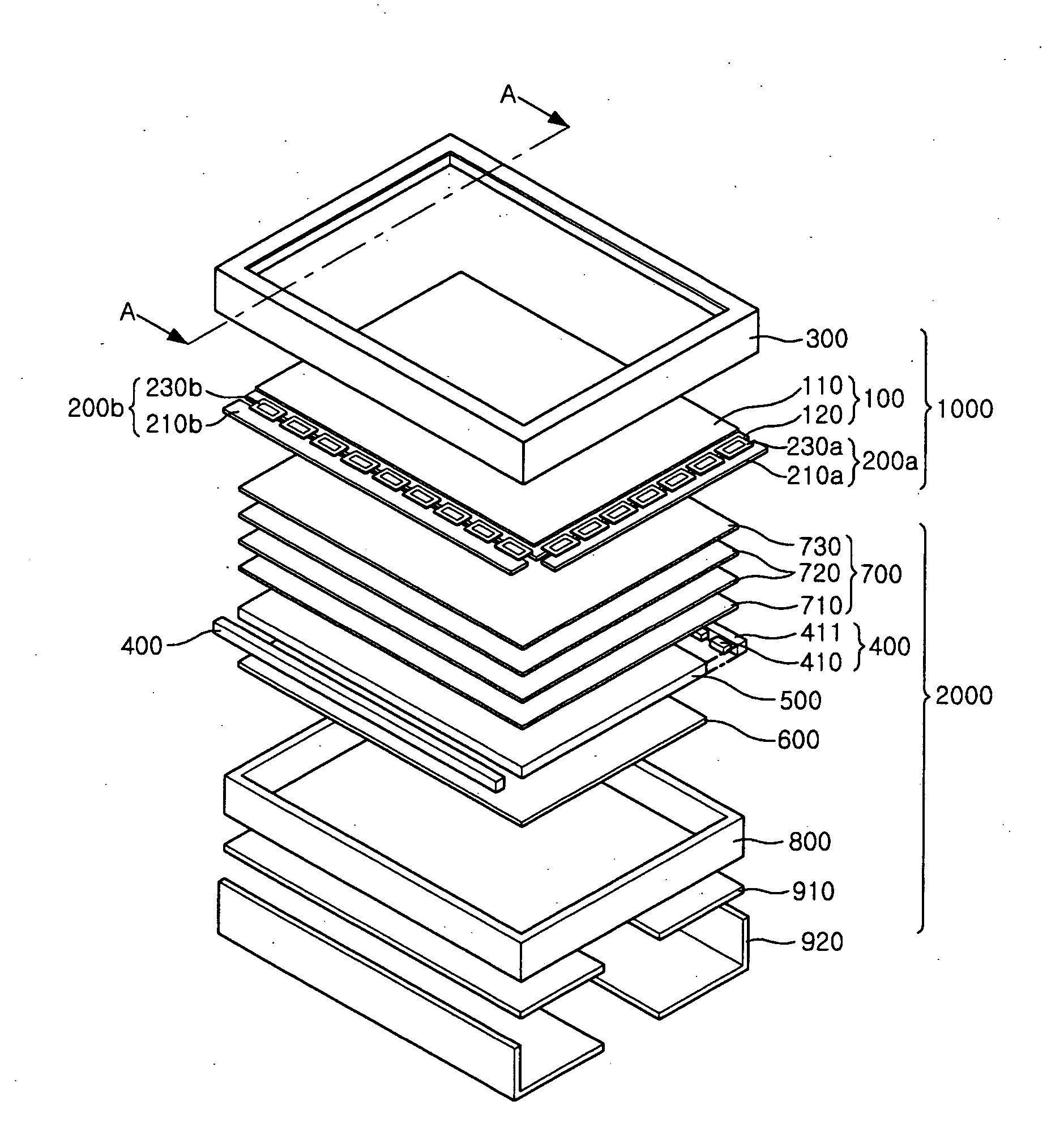
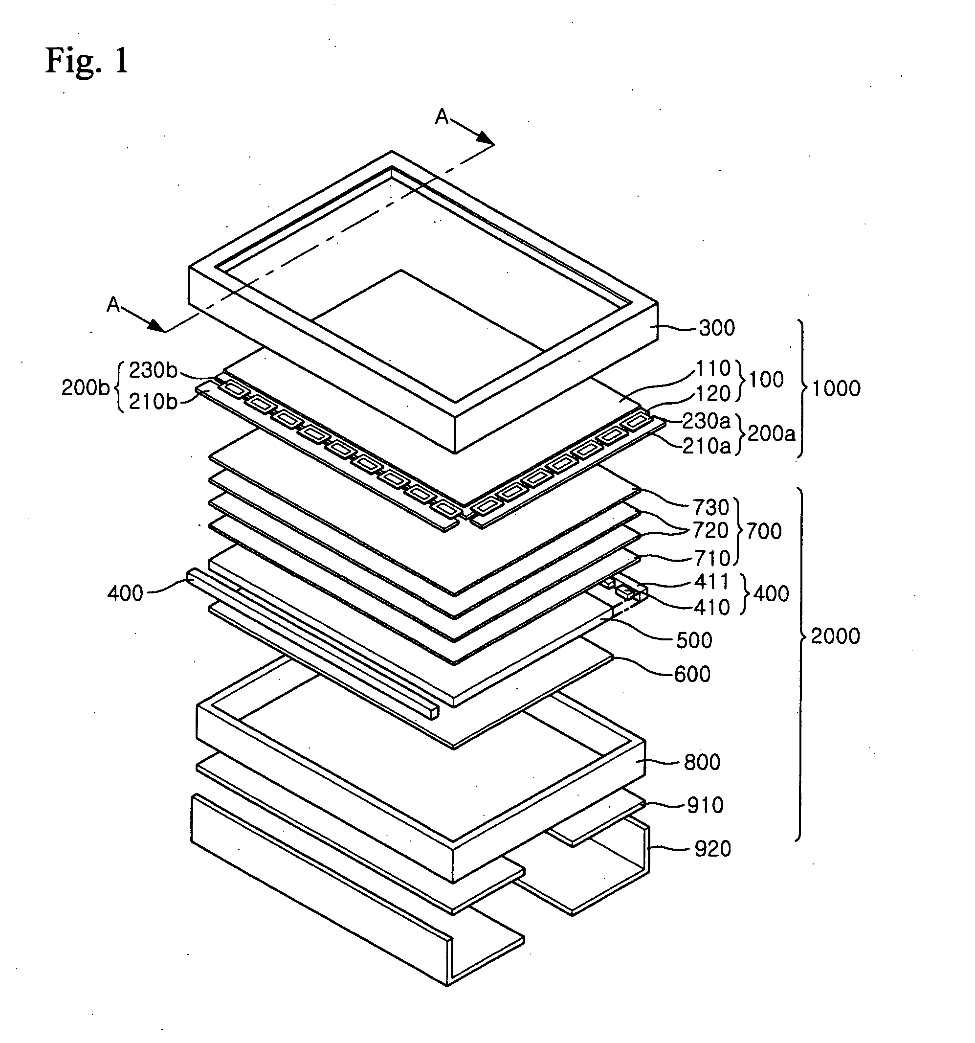
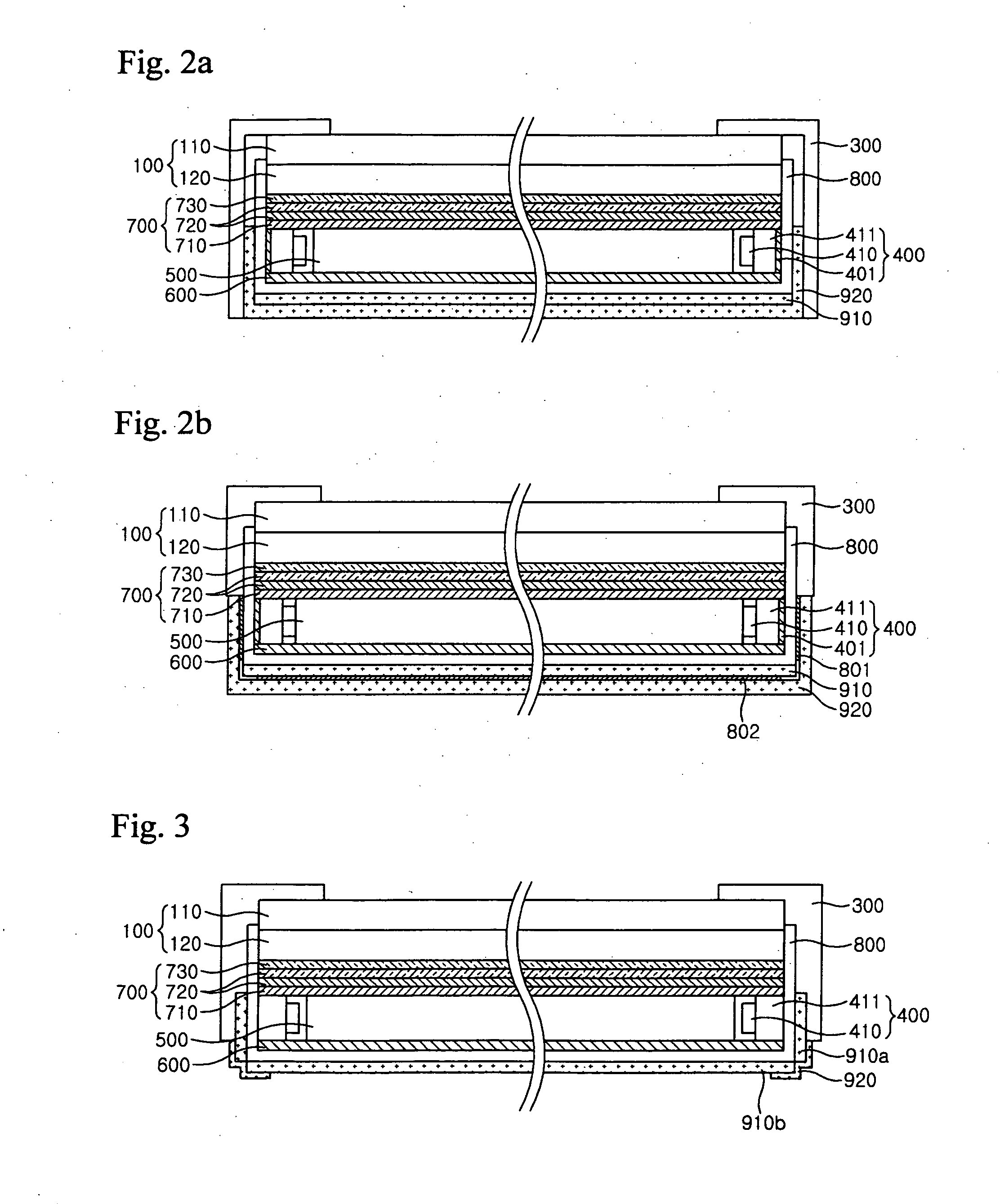
[0036]FIG. 1 is an exploded perspective view of a liquid crystal display device according to a first embodiment of the present invention. FIGS. 2a and 2b are sectional views of the liquid crystal display device taken along line A-A of FIG. 1.

[0037] Referring to FIGS. 1, 2a and 2b, the liquid crystal display (LCD) device according to the first embodiment of the present invention comprises a display assembly 1000 placed at its upper position and a backlight assembly 2000 placed at its lower position.

[0038] The display assembly 1000 includes a liquid crystal display (LCD) panel 100, a driver circuit 200 (200a, 200b), and an upper receiving member 300.

[0039] The LCD panel 100 includes a color filter substrate 110 and a thin film transistor (TFT) substrate 120. Here, the color filter substrate 110 is a substrate having RGB pixels, which are formed through a thin film process and generate a desired color when light passes through the pixels. Coated on the front surface of the color fil...

second embodiment

[0060]FIG. 4 is an exploded perspective view of a liquid crystal display (LCD) device according to a second embodiment of the present invention. FIG. 5 is a sectional view of the LCD device taken along line B-B of FIG. 4. FIG. 6 is a sectional view illustrating the connection of a lower receiving member according to the present invention.

[0061] Referring to FIGS. 4 to 6, the LCD device according to this embodiment comprises a display assembly 1000 and a backlight assembly 2000.

[0062] The display assembly 1000 includes an LCD panel 100, a drive circuit 200 (200a, 200b) and an upper receiving member 300. The LCD panel 100 includes a color filter substrate 110 and a TFT substrate 120.

[0063] The TFT substrate 120 includes a data-side drive IC 111a for transmitting an image signal to a data line of the TFT and a gate-side drive IC 111b for transmitting a gate signal to a gate line of the TFT, in addition to a cell array composed of TFTs and pixel electrodes in a matrix form.

[0064] Th...


PUM


Abstract

A backlight assembly and a liquid crystal display device can discharge heat from the lamp unit to the outside or effectively dissipate the heat. The backlight assembly of the present invention includes a lamp unit, a receiving member for receiving the lamp unit, a first heat dissipation member disposed below the receiving member, and a second heat dissipation for wrapping around a lateral side of the receiving member and the first heat dissipation member. The lamp unit is disposed on an area corresponding to the lateral side of the receiving member. In one embodiment, the first heat dissipation member is a flat plate made of graphite and disposed on an outer side of the bottom of the receiving member. The second heat dissipation member is metal with good thermal conductivity in close contact with the first heat dissipation member and the lateral side of the receiving member where the lamp unit is disposed. Thus, the heat discharged from the lamp unit can be distributed uniformly over the entire area of the receiving member. In addition, the lateral side of the receiving member where the lamp unit is disposed can be replaced with the second heat dissipation member.

Description

BACKGROUND OF THE INVENTION [0001] 1. Field of the Invention [0002] The present invention relates to a backlight assembly and to a liquid crystal display device using the same, and more particularly, to a backlight assembly and a liquid crystal display device using the same, which can reduce edge dark spots occurring in a direct type backlight structure. [0003] 2. Description of the Related Art [0004] In general, liquid crystal display devices have been widely employed in the art due to a variety of advantageous features such as light weight, slim shape, low power consumption, full-color implementation and high resolution. Recently, liquid crystal display devices have been utilized in computers, notebooks, PDAs, telephones, TV sets, audio / video devices and the like. In such liquid crystal display devices, the light transmissivity is controlled to display desired images on liquid crystal display panels, depending upon image signals applied to a plurality of control switches arranged ...

Claims


Application Information

Patent Timeline
IPC IPC(8): F21V7/04
CPCF21V29/004G02B6/0068G02F2001/133628G02B6/0085G02F1/133615G02B6/0073F21V29/74F21V29/89G02F1/133628G02F1/1335
Inventor CHO, JOO WOANLEE, SANG YUKIM, GI CHERLSONG, CHUN-HOLEE, SANG HOONKANG, SEOCK HWAN
Owner SAMSUNG DISPLAY CO LTD
Why Eureka
Try Eureka