Re-entrant cellular multifunctional structure for energy absorption and method of manufacturing and using the same

Inactive Publication Date: 2006-12-21
UNIV OF VIRGINIA ALUMNI PATENTS FOUND
View PDF99 Cites 17 Cited by
  • Summary
  • Abstract
  • Description
  • Claims
  • Application Information

AI Technical Summary

Benefits of technology

[0015] An aspect of an embodiment of the present invention includes a method of efficiently absorbing impact energy during impact loading on a structure. The method comprising: providing the structure comprising a first cellular layer, a second cellular layer, a sacrificial layer there between; interpenetrating the first cellular la

Problems solved by technology

Further, metallic structures for energy absorption are frequently designed to crush, creating a sequence of folds, thereby increasing the volume of material participating in the deformation.
Nonetheless, plastic deformation in such structures is typically localized in regions where bending occurs.
Thus, even during crushing, a significant volume fraction of the metallic structure may remain relatively un-defo

Method used


Image

  • Re-entrant cellular multifunctional structure for energy absorption and method of manufacturing and using the same
  • Re-entrant cellular multifunctional structure for energy absorption and method of manufacturing and using the same
  • Re-entrant cellular multifunctional structure for energy absorption and method of manufacturing and using the same

Examples


Embodiment Construction

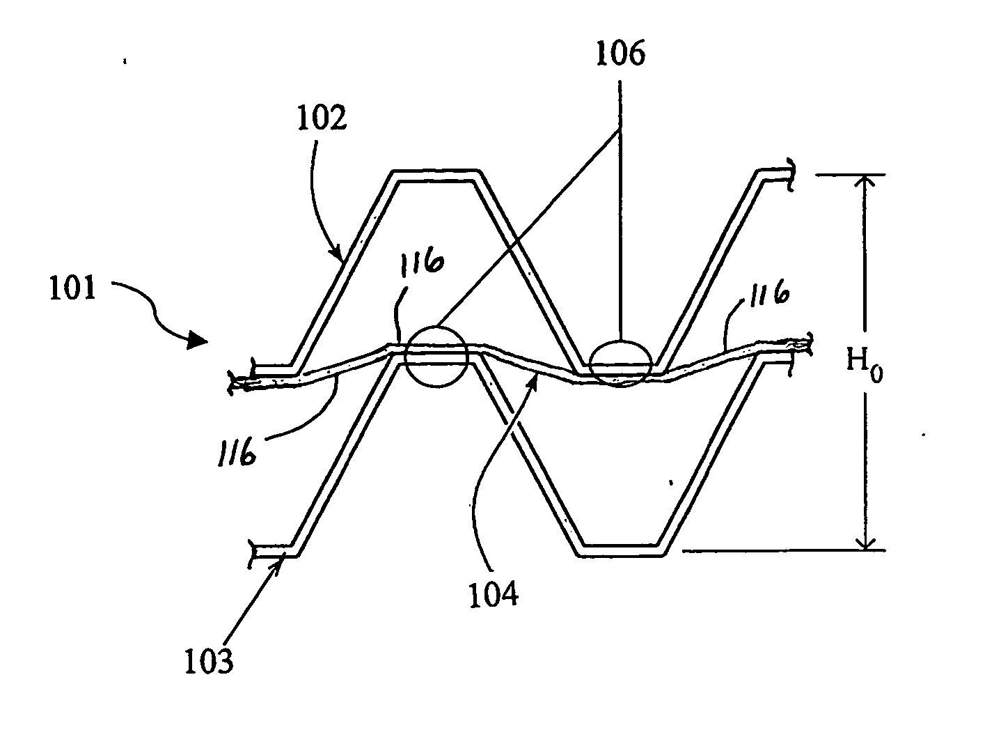
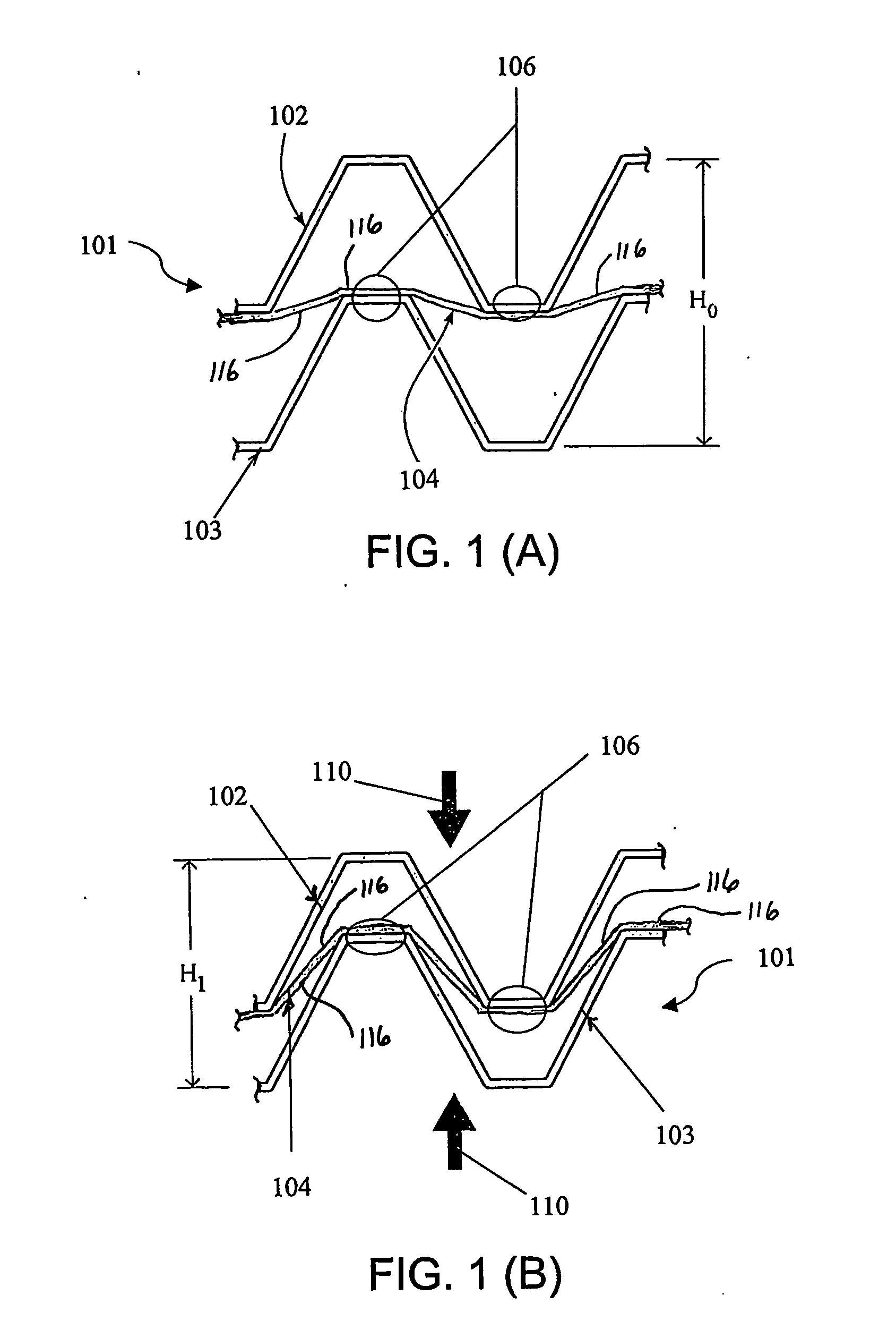
[0021] Referring generally to FIGS. 1(A)-(B), and as will be discussed in greater detail throughout this document, some exemplary embodiments of the present invention provides a multifunctional laminate structure 101 comprised of alternating layers of at least two types. The alternating layers having inter alia the various distinct characteristics. For example, characteristics of a first layer type may be lightweight, structurally efficient cellular design intended to interpenetrate when layers are compressed together as during deformation or impact loading. These layers are schematically represented by the upper cellular layer 102 and the lower cellular layer 103, and are arranged such that they are stacked directly on top of one another (e.g., in analogy with stacking chairs which interpenetrate to take up less space when stacked for storage). Referred to here as ‘cellular’ layers, they remain rigid (i.e., they do not deform) or at least substantially rigid during macroscopic comp...


PUM

PropertyMeasurementUnit
Forceaaaaaaaaaa
Structureaaaaaaaaaa
Tensile propertiesaaaaaaaaaa

Abstract

A cellular composite laminate structure (101) adapted for efficient energy absorption is provided along with the related use and method of manufacture. The structure uses rigid cellular core layers (102, 103) designed to remain rigid during impact loading to channel an imposed compressive force into plastic deformation of deforming sacrificial layers (116). The rigid cellular core layers (102, 103) are arranged such that they will interpenetrate during impact loading while the deforming sacrificial layers (116) are arranged such that they will impede interpenetration of the rigid cellular core layers (102, 103) and be subjected to tensile deformation only. The rigid cellular core layers (102, 103) and deforming sacrificial layers (116) can be formed to create two-dimensional cellular sheet or three-dimensional cellular topology structures. The deforming sacrificial layers (116) can be connected at various points to the rigid cellular core layers (102, 103) or can be connected only at the periphery of the overall structure. Higher strength, rigid materials are contemplated for the rigid cellular core layers (102, 103) while ductile materials are contemplated for the deforming sacrificial layers (116).

Description

RELATED APPLICATIONS [0001] This application claims priority under 35 U.S.C. Section 119(e) of the earlier filing date of U.S. Provisional Application Ser. No. 60 / 473,694, filed on May 28, 2003, entitled “Re-entrant Cellular Composite for Energy Absorption and Method of Manufacturing and Using the Same,” the entire disclosure of which is hereby incorporated by reference herein.US GOVERNMENT RIGHTS [0002] This invention was made with United States Government support under Grant No. 116941-101-GG10464-31340, awarded by the Office of Naval Research. The United States Government has certain rights in the invention.FIELD OF THE INVENTION [0003] The present invention generally relates to cellular structures adapted for energy absorption, and more particularly a cellular multifunctional laminate structure that channels an imposing compressive force into plastic deformation of sacrificial layers of ductile material within the structure. BACKGROUND OF THE INVENTION [0004] The ability of mate...

Claims


Application Information

Patent Timeline
IPC IPC(8): B32B3/10B32B7/022B32B3/00B60R19/18B60R19/22B60R21/04B65D81/05
CPCB22F3/1115B32B3/10B32B5/18B32B7/02Y10T428/24628B60R19/22B60R21/04B65D81/05Y10T428/24273B60R19/18Y10T428/249981B32B7/022B32B2307/558B32B7/12B32B3/266B32B2419/00B32B2605/00
Inventor ELZEY, DANA M.
Owner UNIV OF VIRGINIA ALUMNI PATENTS FOUND
Why Eureka
Try Eureka