Safety fluid transfer cannula

Inactive Publication Date: 2006-12-21
INVIRO MEDICAL DEVICES LTD
View PDF7 Cites 81 Cited by
  • Summary
  • Abstract
  • Description
  • Claims
  • Application Information

AI Technical Summary

Benefits of technology

[0018] It is also a feature of the invention that, as the cannula is removed from a vial, horizontally-oriented, elliptical or

Problems solved by technology

The current healthcare work place, both in the hospital and in the home, offers many professional and personal safety challenges for healthcare workers.
The increasing age of patients, the more complex nature of diseases and the incidence of serious infectious diseases such as HIV and Hepatitis all contribute to increased personal risk and demands for the healthcare worker.
The diminishing number of healthcare workers and their increasing average age exacerbates the problems of recruitment and retention in developed countries.
The migration of skilled healthcare workers from developing countries places additional strains on the scarce human resources in these countries.
Medical device safety initiatives have in some cases been very successful but in others have not been as effective as anticipated or required.
In addition, the design of some safety devices has been too complex, not user friendly, or viewed by some as too expensive to adopt.
Other factors resulting in failure of acceptance include devices which are difficult to train healthcare workers to use, require unusual dexterity or lack sound ergonomic design.
The number of steps involved can be quite large and the time taken

Method used


Image

  • Safety fluid transfer cannula
  • Safety fluid transfer cannula
  • Safety fluid transfer cannula

Examples


Embodiment Construction

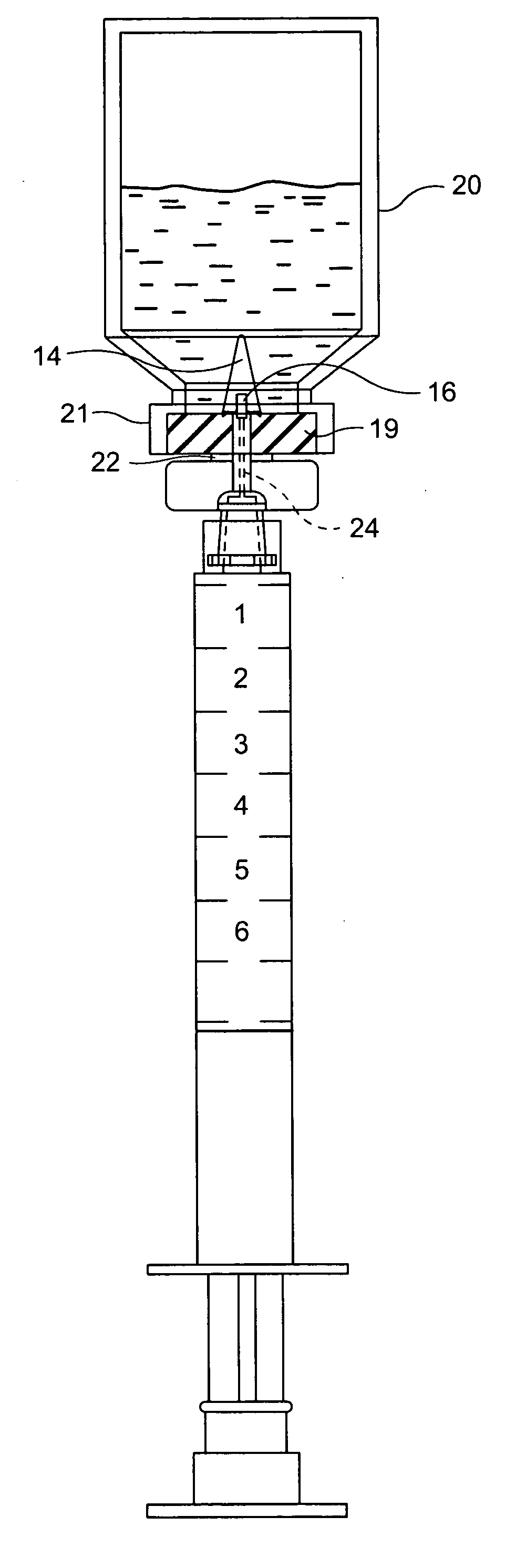
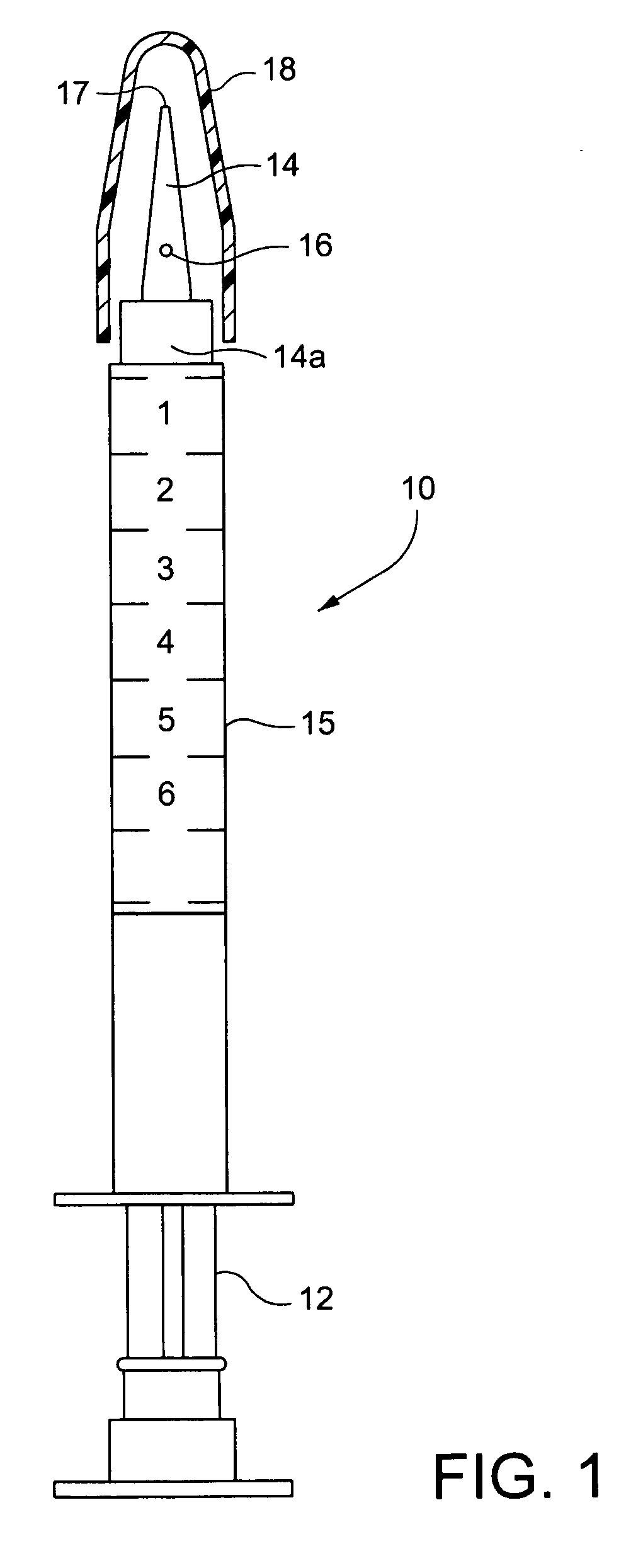
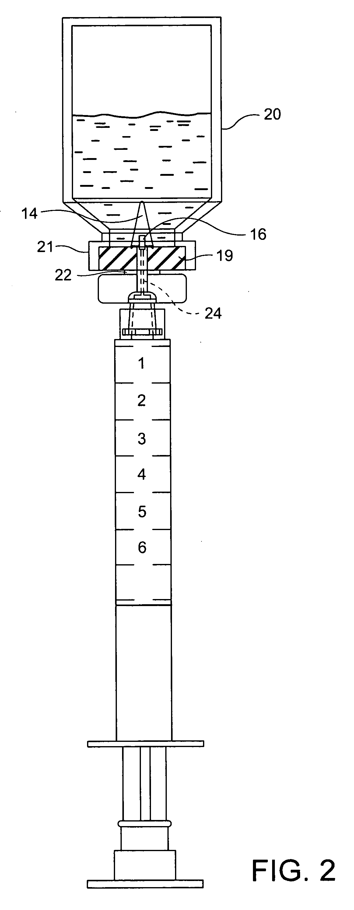
[0029] Referring to the drawings, particularly FIG. 1, a syringe generally designated 10 is illustrated including a plunger 12 and an integral cannula manufactured as a syringe barrel extension shown as 14 and 14A with a lumen opening or port 16 through a side surface of the integral cannula in communication with a passage, preferably axial through the cannula, in turn an extension of and therefore in communication with the interior of the syringe barrel 15. The tip 17 of the cannula 14 is semi-sharp, enabling the cannula 14 for penetration through the septum, i.e., an elastomeric membrane stopper of a vial, or a septum (possibly pre-slit) of an IV line access port. The relative bluntness of the tip 17 generally precludes penetration of the skin or of a protective glove as often worn by an individual using the syringe 10. The solid tip ensures that the insertion of the cannula through a membrane does not core the membrane or produce unwanted particles during insertion. The side open...


PUM


Abstract

A cannula for transferring fluid relative to a vial or intravenous port having an elastomeric membrane includes: a cannula body having first and second opposite ends; the first end terminating in a tip for penetrating the elastomeric membrane; the body having a passage opening through the second end and extending within the cannula body towards the first end, the passage opening through at least one horizontal-oriented port through a side surface of the cannula body thereby to enable flow of fluid along the passage and between the opening through the second end and the side port. An axial width of the port is smaller than a thickness dimension of a vial through which the cannula tip is to be inserted. A related method is also described.

Description

CROSS-REFERENCES TO RELATED APPLICATIONS [0001] This application is a continuation-in-part of application Ser. No. 11 / 346,302, filed Feb. 3, 2006, which in turn claims priority from U.S. Provisional Patent Application Ser. No. 60 / 690,520, filed Jun. 15, 2005.BACKGROUND OF THE INVENTION [0002] The present invention relates to a fluid aspiration and injection cannula or syringe barrel extension having safety features to preclude needle stick injuries and particularly relates to an aspiration / injection cannula particularly useful for withdrawing fluid from one or more standard vials, e.g., a medication vial into a standard hypodermic syringe and / or for injecting fluid into a similar vial or other containers or access ports such as the port of an intravenous (IV) line in a manner permitting safe transfer of fluid minimizing or eliminating the potential for accidental needle stick injuries. In the unlikely event that a skin penetration did occur with the subject cannula, even if it is co...

Claims


Application Information

Patent Timeline
IPC IPC(8): A61B19/00
CPCA61J1/2096A61J2200/10A61J2001/201A61J1/201
Inventor SHARP, FRASER R.
Owner INVIRO MEDICAL DEVICES LTD
Why Eureka
Try Eureka