Stent with mechanically interlocking struts and methods for making the same

a technology of mechanical interlocking and stents, which is applied in the field of stents, can solve the problems that the female component of the mechanical interlock cannot be pushed outwardly, and achieve the effects of facilitating delivery, and increasing the flexibility of the sten

Inactive Publication Date: 2006-12-21
OLSEN DANIEL +1
View PDF9 Cites 18 Cited by
  • Summary
  • Abstract
  • Description
  • Claims
  • Application Information

AI Technical Summary

Benefits of technology

[0011] The systems and methods of the invention provide a stent with increased flexibility. The increased flexibility of the stent more easily accommodates delivery of the stent to a blood vessel or other passageway in the body of a patient. The increased flexibility of the stent als...

Problems solved by technology

Likewise, the female component of the mechanical interlock is unable t...

Method used


Image

  • Stent with mechanically interlocking struts and methods for making the same
  • Stent with mechanically interlocking struts and methods for making the same
  • Stent with mechanically interlocking struts and methods for making the same

Examples


Embodiment Construction

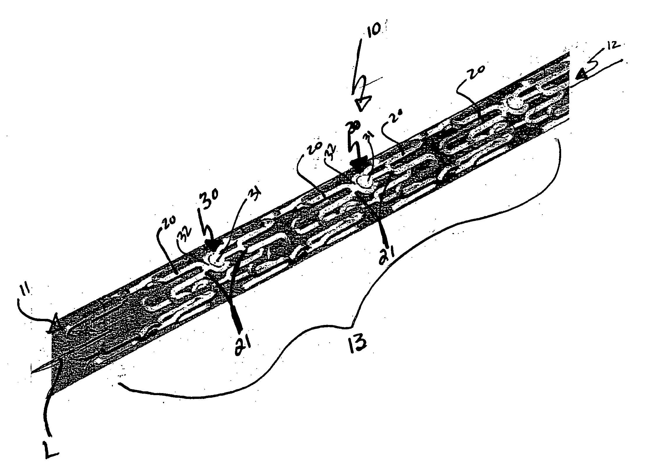
[0046]FIG. 5 illustrates a cylindrical stent 10 having a first end 11, a second end 12 opposite the first end 11, and an intermediate section 13 extending therebetween the first and second ends 11, 12. A longitudinal axis L extends throughout the stent 10 between the first and second ends 11, 12 as well. Hereafter, any reference to “inward” or “inwardly” movement is understood as movement towards the longitudinal axis L, unless otherwise indicated. The intermediate section 13 of the stent 10 further comprises a series of adjacent strut sections 20 comprised of undulating waves that extend longitudinally between the first and second ends 11, 12. A closed end 21 of the undulating wave of one strut section 20 is generally aligned opposite a closed end 21 of the undulating wave of an adjacent strut section 20 so as to form designated pairs of longitudinally adjacent strut sections 20. Each designated pair of longitudinally adjacent strut sections 20 are connected via a mechanical interl...


PUM

PropertyMeasurementUnit
Angleaaaaaaaaaa
Thicknessaaaaaaaaaa
Flexibilityaaaaaaaaaa

Abstract

A stent having mechanically interlocked strut sections and methods of making the same. Sets of longitudinally adjacent strut sections have closed ends that are mechanically interlocked by laser cut pairs of corresponding male and female components. The contours of the male and female components generally preclude the respective male components received therein from escaping from the female components even as the dynamics of the vascular or other system within which the stent is placed urges a male component on an opposite side of a set out of a corresponding female component. Rotational movement of the mechanically interlocked male components remains generally unimpeded. Designated pairs of mechanically interlocked strut sections within a set of longitudinally adjacent strut sections are diametrically opposed, or otherwise oriented, relative to one another which keeps the sections together. Sets of neighboring mechanically interlocked adjacent strut sections are arranged out of phase relative to one another in order to increase the rigidity and flexibility of the stent.

Description

BACKGROUND OF THE INVENTION [0001] 1. Field of the Invention [0002] The invention generally relates to a stent having mechanically interlocking struts and methods for making the same. More specifically, the invention relates to stents having mechanical interlocks comprised of male and female components that are movably connected to one another at ends of designated sets of adjacent struts. [0003] 2. Related Art [0004] Intraluminal endovascular stents are well-known. Such stents are often used for repairing blood vessels narrowed or occluded by disease, for example, or for use within other body passageways or ducts. Ideally, the stent will conform to the contours and functions of the blood vessel or other body passageway in which the stent is to be deployed. Increased flexibility of the stent generally eases delivery of the stent and increases the conformability of the stent to the environment in which the stent is deployed. [0005]FIGS. 1a &1b show structures that have been used as i...

Claims


Application Information

Patent Timeline
IPC IPC(8): A61F2/06A61F2/82
CPCA61F2/91A61F2/915A61F2002/828A61F2002/91508A61F2002/91516A61F2230/0054A61F2002/91558A61F2002/91575A61F2002/91591B23K26/38A61F2002/91533
Inventor OLSEN, DANIELMASON, JAY
Owner OLSEN DANIEL
Why Eureka
Try Eureka