
Method and apparatus for scanning corrosion and surface defects

a surface defect and corrosion technology, applied in the field of materials inspection, can solve the problems of unable to determine the remaining life span of the corroded pipeline, dangerous and expensive damage, etc., and achieve the effect of accurate and accurate information on corrosion and accurate determination of the surface conditions of the corrosion pi

Inactive Publication Date: 2006-12-28
DE MEURECHY GUIDO D K
View PDF23 Cites 122 Cited by
  • Summary
  • Abstract
  • Description
  • Claims
  • Application Information

AI Technical Summary

Benefits of technology

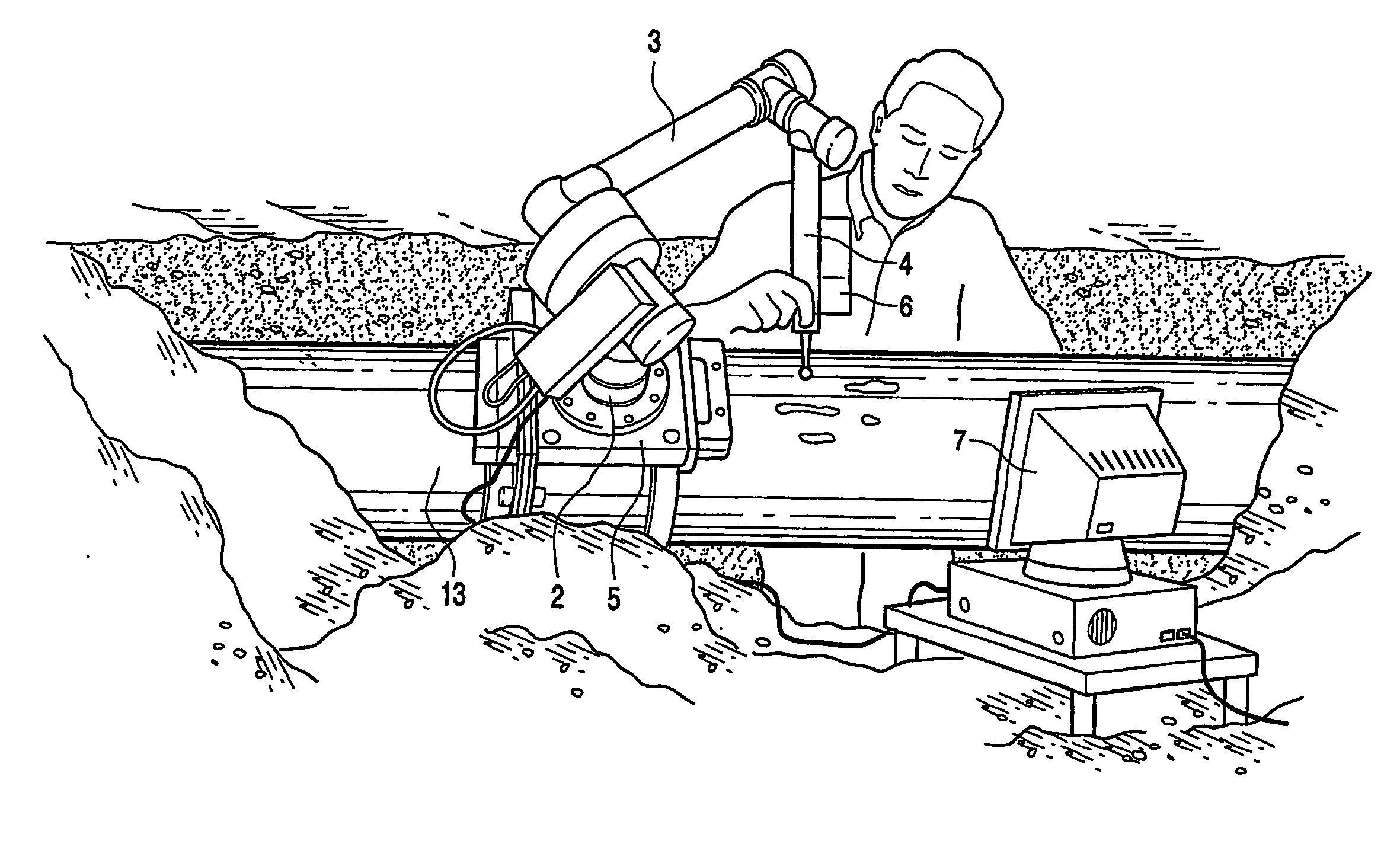
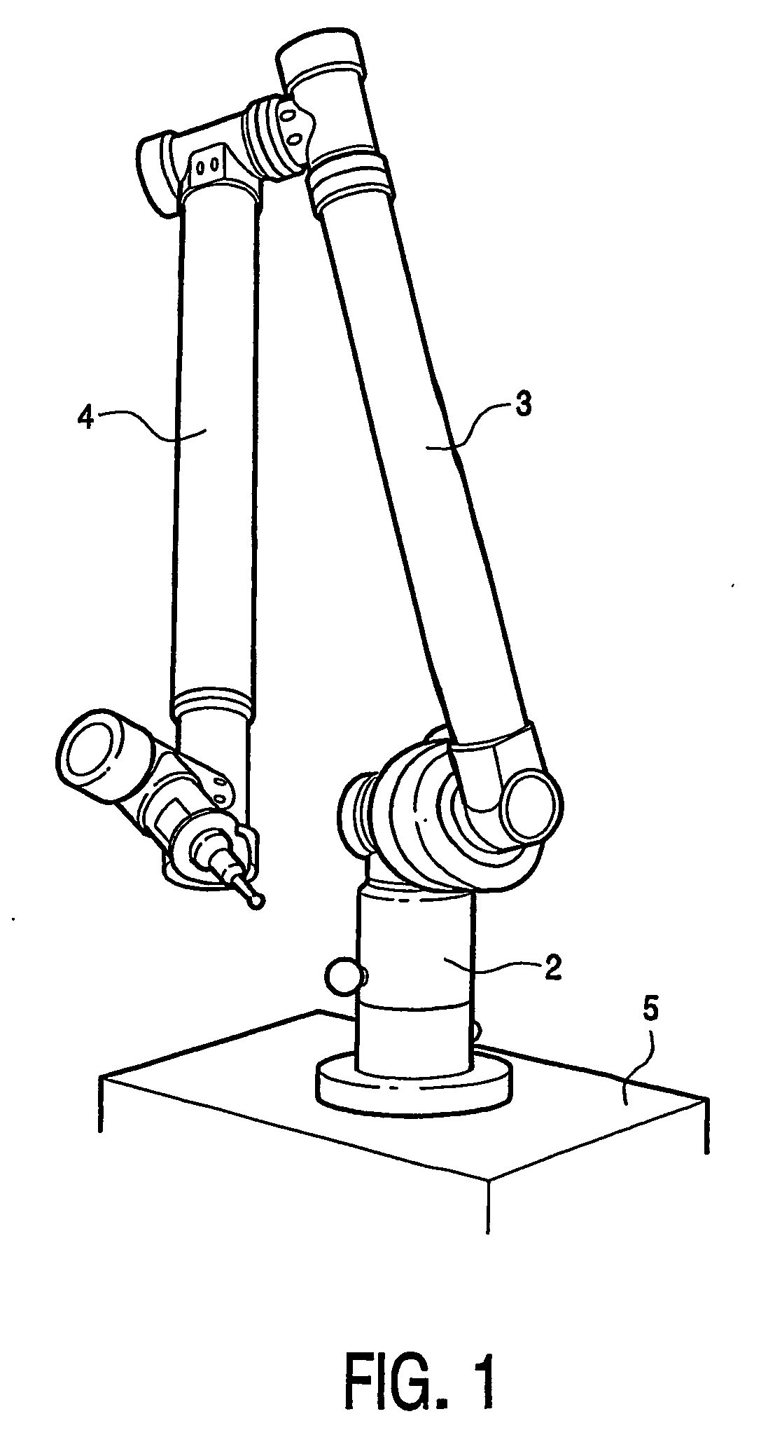
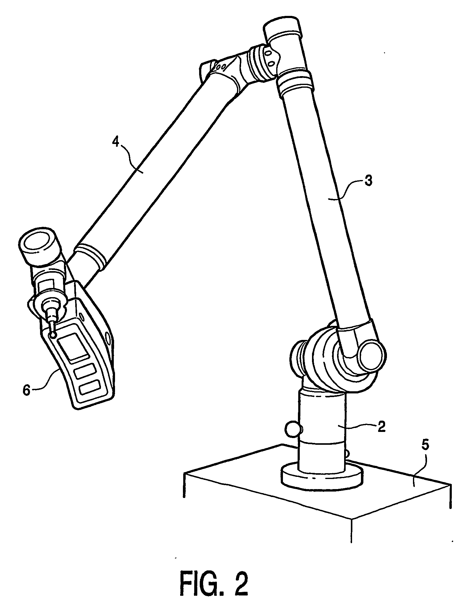
"The present invention provides an improved method and apparatus for determining the life span for secure use of a pipeline. The method involves defining an area for surface corrosion analysis on the pipeline, providing a corrosion scanning system for scanning the defined area, and measuring corrosion on the surface of the pipeline by moving the corrosion scanning system in three dimensions. The method can identify and locate areas of corrosion on the pipeline and determine the remaining wall-thickness and strength of the pipeline. The corrosion scanning system is constructed in such a way as to allow it to be positioned in all possible directions in a three-dimensional plane, providing more accurate and correct evaluation of the surface condition data of corrosion pits in the pipeline. The invention also allows for the identification and characterization of areas on the pipeline that are susceptible to corrosion."

Problems solved by technology

In gas and liquid transmission pipelines corrosion can cause dangerous and expensive damages and assessment of pipe condition on a periodic basis is required.
However, such methods do not enable to determine the remaining life span for secure use of the corroded pipeline.

Method used


Image

  • Method and apparatus for scanning corrosion and surface defects
  • Method and apparatus for scanning corrosion and surface defects
  • Method and apparatus for scanning corrosion and surface defects

Examples


Embodiment Construction

[0048] Corrosion is a naturally occurring phenomenon commonly defined as the deterioration of a substance, usually metal, or its properties because of a reaction with the environment. Corrosion can cause dangerous and expensive damages to objects such as highway bridges, gas and liquid transmission pipelines, railroads, motor vehicles, aircrafts, ships, cranes, petroleum refining, chemical, petrochemical and pharmaceutical production plants, nuclear power stations, etc. . . . Corrosion can lead to structural failure, loss of life, loss of capital investment, and environmental damage and should therefore be detected, measured, mapped and evaluated.

[0049] A common misconception is that corrosion damage happens at the same rate and by the same corrosion mechanism all the time, which is in fact not the case. Corrosion takes place in episodes that are related to specific types of operational situation, e.g. caused by fluctuations in temperature or interaction between changed product che...


PUM

PropertyMeasurementUnit
frequenciesaaaaaaaaaa
velocityaaaaaaaaaa
areaaaaaaaaaaa

Abstract

The present invention relates to a method and an apparatus for determining the life span for secure use of a pipeline comprising the steps of a) defining an area for surface corrosion analysis on the pipeline, b) providing a corrosion scanning system for scanning the defined area on the pipeline, c) localizing and measuring the corrosion on the surface of the defined area by means of the corrosion scanning system, d) determining the remaining wall-thickness of the pipeline at the defined area by means of the corrosion scanning system, and e) processing the surface condition data related to corrosion at the defined area obtained in steps c) and d) to determine the life span for secure use of the pipeline. In another aspect the present invention relates to a corrosion scanning system for performing for performing the method according to the invention. In another aspect the invention relates to a prediction system for predicting the secure life span of a pipeline.

Description

FIELD OF THE INVENTION [0001] The present invention relates to the field of inspection of materials for the presence of corrosion or surface defects, such as dents, third party damage, etc. . . . In particular, the present invention relates to a method and an apparatus for determining and analyzing corrosion in or on a pipeline. In addition; the invention also relates to a method and apparatus for determining the life span for secure use of a pipeline. In another aspect the invention relates to a prediction system for predicting the secure life span of a pipeline. BACKGROUND OF THE INVENTION [0002] Corrosion on the external or internal surfaces of in-service pipes, tanks, or other industrial assets reduces the integrity of the material and potentially reduces the service life of the equipment. Defects may have various forms and may be initiated by one or more mechanisms potentially resulting in corrosion and / or cracking. These factors affect a wide range of materials and bridge many...

Claims


Application Information

Patent Timeline
Patent Type & Authority Applications(United States)
IPC IPC(8): G01D18/00G01N17/00G01N21/95G01N21/952G01N21/954
CPCG01N17/006G01N21/49G01N21/9515G01N21/952G01N21/954G01N29/041G01N2291/2634G01N29/2418G01N2291/014G01N2291/015G01N2291/0258G01N2291/0423G01N2291/044G01N29/07
Inventor DE MEURECHY, GUIDO D. K.
Owner DE MEURECHY GUIDO D K
Learn More