Catalytic combustion type gas sensor

a gas sensor and catalytic combustion technology, applied in the field can solve the problems of inspectors visiting and inspecting, the problem of catalytic combustion type gas sensors having a lot of trouble, and the inspection of the actual gas takes a lot of time, so as to eliminate an excessive cost and increase the safety of the system or equipment

Inactive Publication Date: 2006-12-28
CITIZEN WATCH CO LTD
View PDF2 Cites 26 Cited by
  • Summary
  • Abstract
  • Description
  • Claims
  • Application Information

AI Technical Summary

Benefits of technology

[0026] Further, if the gas to be sensed is a hydrogen gas, the catalytic combustion type gas sensor is very effective as a gas sensor for sensing leakage of the hydrogen gas in a fuel cell system.
[0027] The catalytic combustion type gas sensor according to the invention can sense a malfunction such as deterioration or the like upon occurrence of it by the gas sensor itself without inspection using an actual gas and inform of the occurrence of malfunction, so that the gas sensor can increase the safety of a system or equipment using a combustible gas as well as eliminate an excessive cost required for check.

Problems solved by technology

However, the catalytic combustion type gas sensor has a problem.
The problem is that since the sensor is to be used for a long time, deterioration of the sensing element or the like and malfunction of circuits may occur, but such an abnormal state, if occurring, is not known because an actual gas leakage rarely occurs.
However, periodical inspection using an actual gas takes a lot of trouble, and it is difficult, in particular, for an inspector to visit and inspect individually the gas sensor provided in a small-size household system.
Another problem is that provision of the gas sensors in two lines leads to an increased cost, and therefore it is difficult to employ the gas sensors in two lines in the small-size system.
Even if the gas sensors in two lines are provided, both of the sensors might possibly malfunction.

Method used


Image

  • Catalytic combustion type gas sensor
  • Catalytic combustion type gas sensor
  • Catalytic combustion type gas sensor

Examples


Embodiment Construction

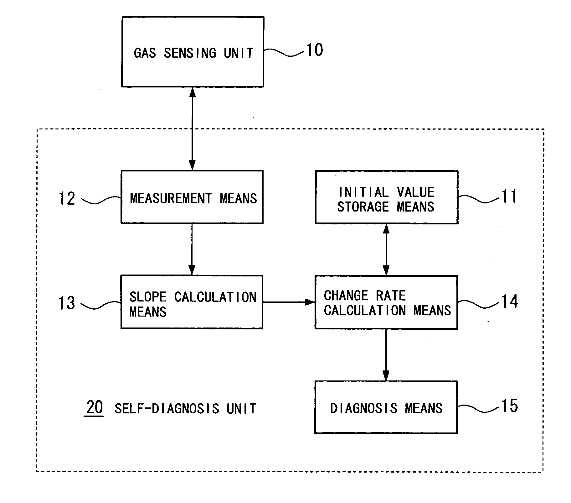
[0040] Hereinafter, a preferred embodiment for carrying out the invention will be concretely described with reference to the drawings.

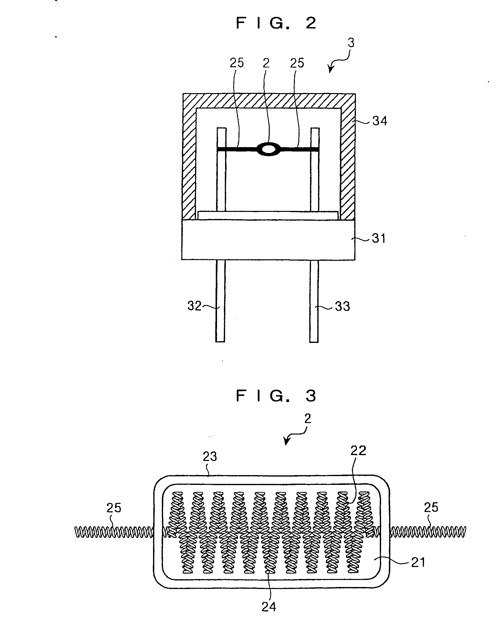
[0041]FIG. 2 is a partial cross-sectional view showing a configuration of a sensor main body to be used in one embodiment of a catalytic combustion type gas sensor according to the invention.

[0042] A sensor main body 3 has lead portions 25 on both sides of a sensing element 2 which are secured to electrode pins 32 and 33 for external connection penetrating a mount base 31 in a plate shape made of ceramic or resin. Further, a compensation element is provided side-by-side with the sensing element 2, though not shown in this drawing, which includes a heater coil having the same configuration and electric property as those of a heater coil of the sensing element 2. The sensing element 2 and the compensation element are surrounded by the mount base 31 and an explosion-proof structure 34 composed of a metal net having gas permeability or a sintered compac...


PUM

PropertyMeasurementUnit
diameteraaaaaaaaaa
diameteraaaaaaaaaa
diagnostic voltageaaaaaaaaaa

Abstract

A catalytic combustion type gas sensor includes a gas sensing unit 10, in which a sensing element having a heater coil embedded in a thermal conduction layer provided with an oxidation catalyst for causing a gas to be sensed to combust by contact, a compensation element having an equivalent heater coil embedded in a thermal conduction layer having no oxidation catalyst, and two resistor elements constitute a Wheatstone bridge circuit, outputs a voltage between the connection point of the sensing element and the compensation element and the connection point of the two resistor elements, as a detection signal, wherein a self-diagnosis unit is provided which diagnoses a sensor abnormality by comparing the slope of changes in voltage of the detection signal relative to changes in the voltage value of the direct-current voltage to be applied across the Wheatstone bridge circuit in an initial state and the slope of changes in voltage of the measurement value of the detection signal relative to changes in the voltage value of the direct-current voltage to be applied in a usage state.

Description

BACKGROUND OF THE INVENTION [0001] 1. Field of the Invention [0002] The present invention relates to a catalytic combustion type gas sensor for sensing leakage of various kinds of gasses and, more particularly, to a catalytic combustion type gas sensor configured to be able to self-diagnose deterioration or operation abnormality due to use for a long time. [0003] 2. Description of the Related Art [0004] Conventionally, a catalytic combustion type gas sensor has been known as a sensor for sensing combustible gasses such as a hydrogen gas, a methane gas, and so on. The catalytic combustion type gas sensor employs a sensing element, in which a heater coil is embedded in a thermal conduction layer (catalyst carrier) having an oxidation catalyst covering its surface or carrying the catalyst for causing a gas to be sensed to combust (oxidize) by contact, and energizes the heater coil of the sensing element to heat it to a predetermined temperature, so that when a combustible gas comes int...

Claims


Application Information

Patent Timeline
Patent Type & Authority Applications(United States)
IPC IPC(8): B23K9/00B23K9/02
CPCG01N33/005G01N27/16
Inventor TAKAHASHI, IKUO
Owner CITIZEN WATCH CO LTD
Why Eureka
Try Eureka