Mounting structure of on-vehicle circuit unit and on-vehicle circuit unit

a technology of on-vehicle circuit unit and mounting structure, which is applied in the direction of vessel parts, lighting and heating apparatus, vessel construction, etc., can solve the problems of affecting the normal operation of the circuit, and the effect of reducing the minute clearance is not easy to achiev

Active Publication Date: 2006-12-28
AUTONETWORKS TECH LTD +2
View PDF41 Cites 11 Cited by
  • Summary
  • Abstract
  • Description
  • Claims
  • Application Information

AI Technical Summary

Benefits of technology

[0007] In view of the foregoing problems, an object of the present invention is to provide a mounting structure of an on-vehicle circuit unit having good cooling performance of a heat radiating member with the minute clearances between a heat radiating member and a body being effectively reduced while the occurrence of impact and noise caused by vibrations of a vehicle are avoided.
[0023] The heat radiating member may have any actual shape. However, if a heat radiating member is formed of a metal plate with a mounting part extending with a step from an edge of the metal plate, the heat radiating member has a simple structure and can ensure an appropriate clearance between the outer surface of the heat radiating member and the body.

Problems solved by technology

However, in reality, due to unevenness (projections and depressions), warp, flexures and the like existing on the outer surface of the heat radiating board, minute clearances are likely to be scattered between the outer surface of the heat radiating board and the body surface.
Such minute clearances retain water which may cause problems such as, it may cause rust.
Impacts caused by repetitive abutment of this portion against the body surface following vibrations of the vehicle may have negative effects on the normal operation of the circuit and may cause noise.
However, even with such a configuration, it cannot be expected to effectively reduce the minute clearances.
Furthermore, the space required in order to mount the control box in a vehicle body is limited so that, for example, in the case of mounting the control box in a narrow engine room, it is actually a difficult operation to fix the entire periphery of the heat radiating board to a side wall of the body.

Method used


Image

  • Mounting structure of on-vehicle circuit unit and on-vehicle circuit unit
  • Mounting structure of on-vehicle circuit unit and on-vehicle circuit unit
  • Mounting structure of on-vehicle circuit unit and on-vehicle circuit unit

Examples


Embodiment Construction

[0035] The preferred embodiments of this invention are next described with reference to the accompanying drawings. The preferred embodiments described herein is of the type wherein the present invention is applied to a circuit unit U which comprises a power distribution circuit for distributing power from a common power supply to a plurality of on-vehicle devices. However, the present invention is not limited to this, but can also be widely applied to a circuit unit for forming various circuits.

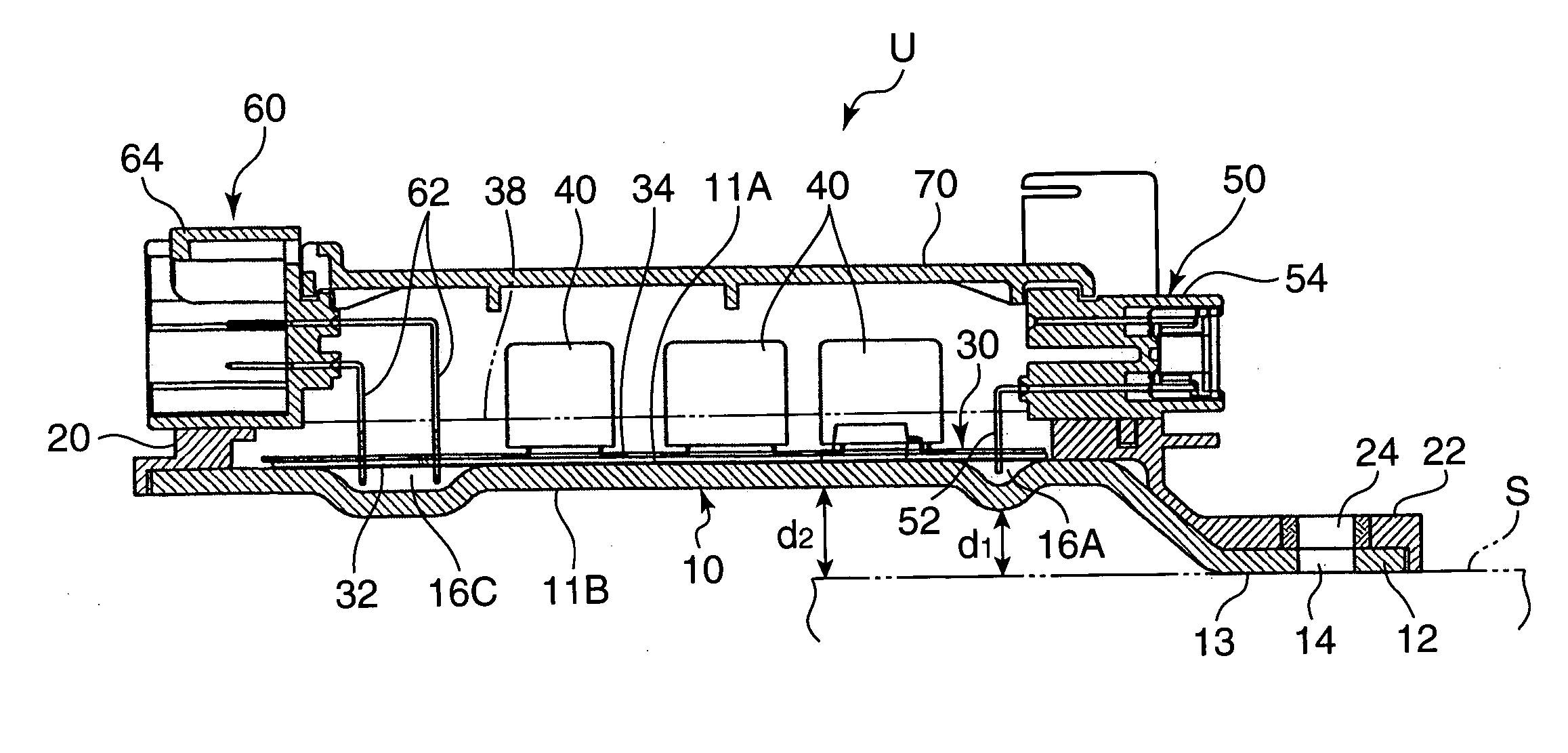
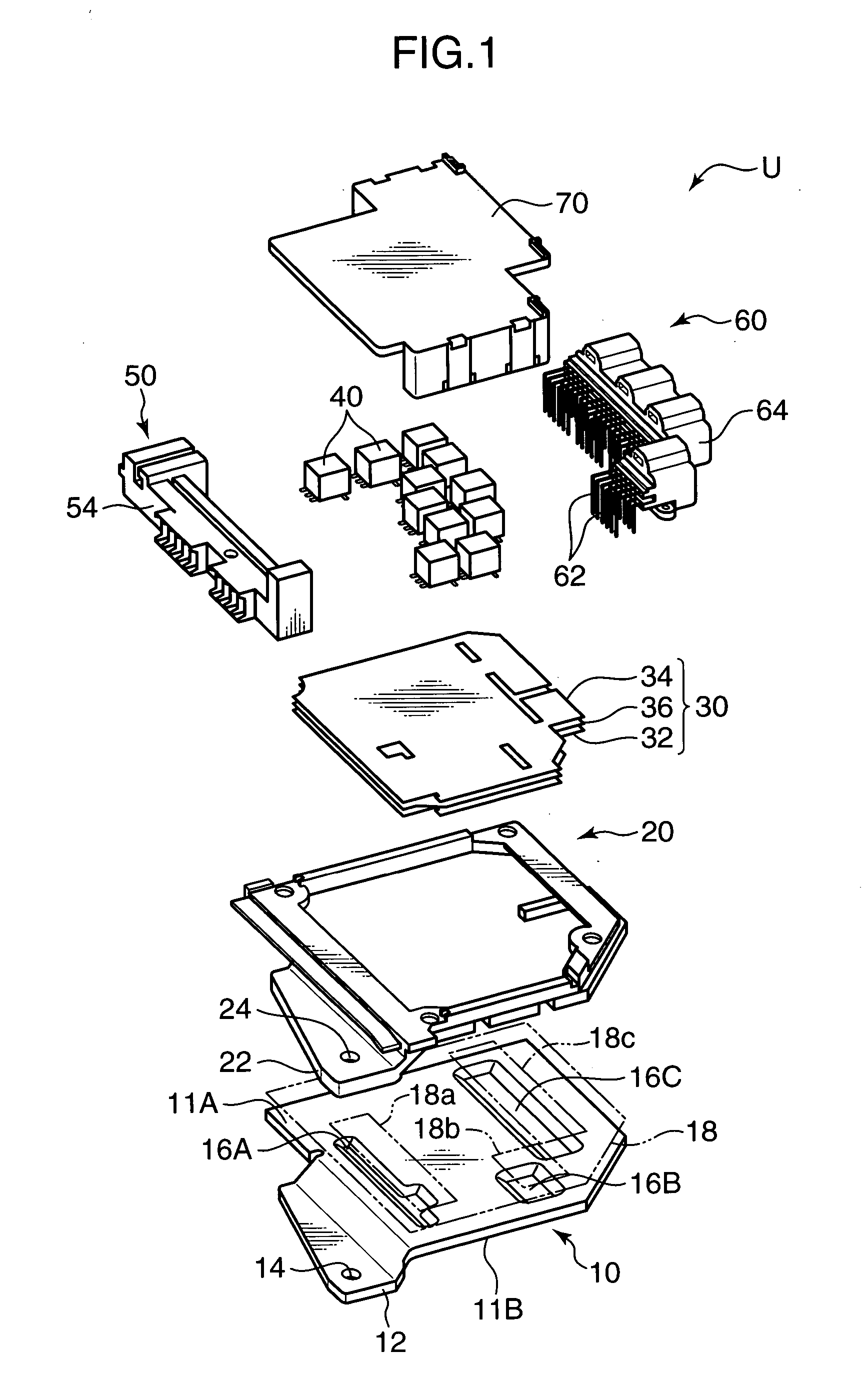
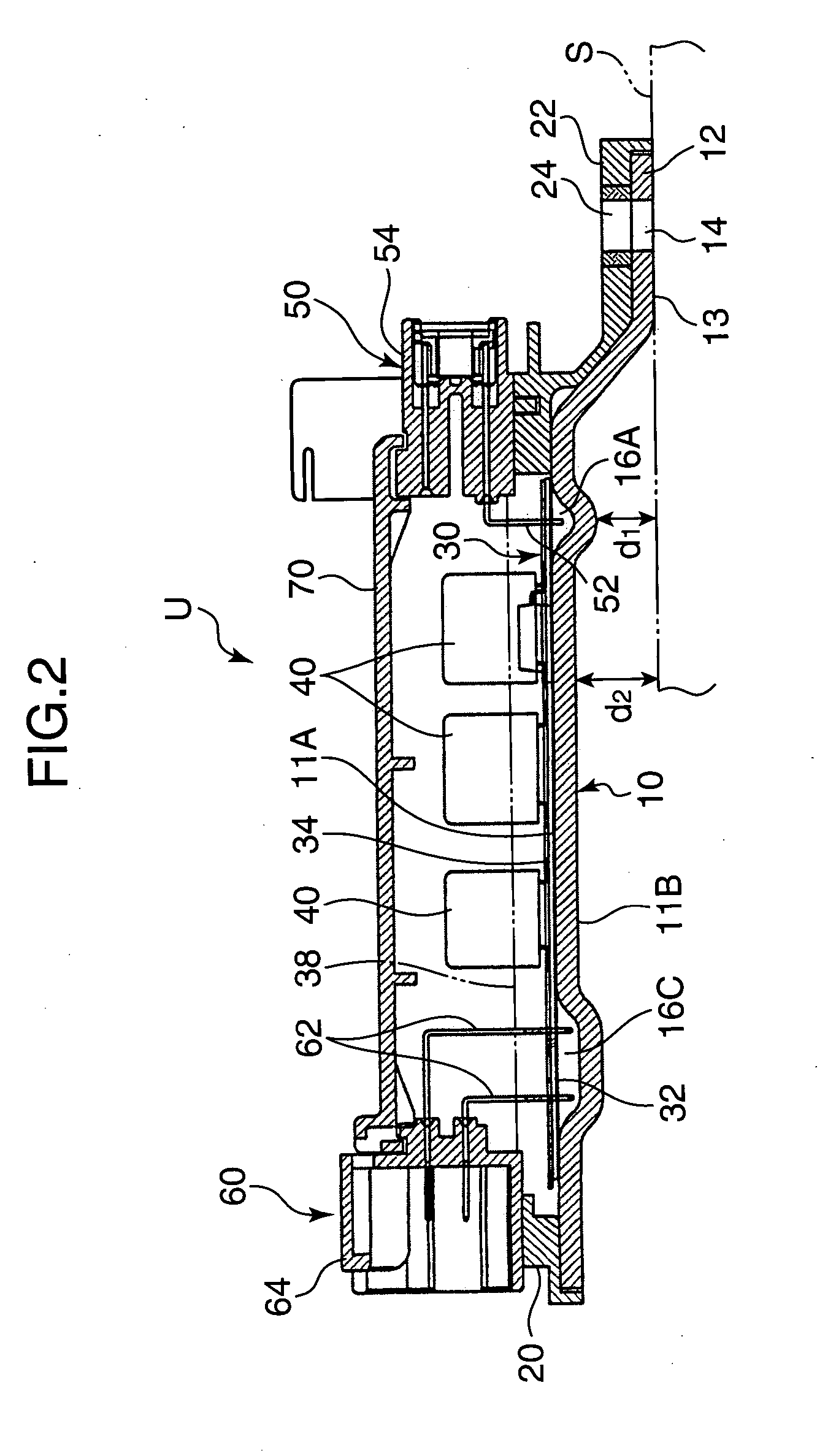
[0036] The circuit unit U shown in FIG. 1 and FIG. 2 comprises a heat radiating plate (heat radiating member) 10, a casing 20 and a sheet-shaped circuit board 30. Board mounted elements 40 and connectors 50 and 60 are mounted on the circuit board 30. A cover 70 for covering the circuit board 30 is to be installed over both connectors 50 and 60.

[0037] The heat radiating plate 10 is formed of a metal plate such as aluminum alloy, or the like having good heat conductivity. An outer surface (bo...


PUM


Abstract

It is an object to effectively reduce minute clearances generated between a heat radiating member and a vehicle body and ensure good cooling performance while avoiding the occurrence of impact and noise caused by the vibration of a vehicle. A circuit unit U is mounted such that an outer surface 11B of the heat radiating member 10 to which the circuit body 30 is fixed faces a body surface S of the vehicle with a clearance. Preferably, the mounting part 12 fixed to the body of the vehicle is extended, the surface 13 of the mounting part 12 which is in contact with the body is positioned to be substantially parallel to the outer surface 11B of the heat radiating member and a step is provided in both surfaces 13, 11B. In a mounted state, the body and the outer surface 11B of the heat radiating member are facing each other in a substantially parallel state and a clearance is formed between the body and the outer surface of the heat radiating member over the entire area excluding the mounting part 12.

Description

FIELD OF THE INVENTION [0001] The present invention relates to an on-vehicle circuit unit for use in a power distributor for distributing electric power from a power supply installed in a vehicle to on-vehicle devices, or the like, and to a mounting structure for the on-vehicle circuit unit. BACKGROUND ART [0002] Conventionally, circuit units comprising a power distribution circuit configured by stacking a plurality of bus bar boards, and having fuses and relay switches assembled thereon have generally been known as a means for distributing electric power from a common on-vehicle power supply to each on-vehicle device. In order to achieve reduction in size of the circuit unit, it has been proposed to bond a bus bar with a control circuit member, or use semiconductor switching elements such as FETs in place of relays. [0003] However, such a circuit unit is likely to generate heat due to a relatively large current flowing in the bus bars. More particularly, in view of large amounts of...

Claims


Application Information

Patent Timeline
Patent Type & Authority Applications(United States)
IPC IPC(8): F24J3/00B60R16/02B60R16/023H02G3/08H05K7/20
CPCB60R16/0239
Inventor TOMIKAWA, TADASHIYAMANE, SHIGEKIKANO, TOMOKIHOSOKAWA, TSUYOSHI
Owner AUTONETWORKS TECH LTD
Why Eureka
Try Eureka