Coordinate detection system for a display monitor

a detection system and display monitor technology, applied in the field of user input apparatus, can solve the problems of difficult and expensive manufacture of display units, physical contact for providing straight forward interactivity is not the best option, and achieve the effects of increasing the selectivity of light incident, enhancing the selectivity of monochromatic light, and increasing the selectivity of electrical signals

Inactive Publication Date: 2006-12-28
KONINKLIJKE PHILIPS ELECTRONICS NV
View PDF7 Cites 70 Cited by
  • Summary
  • Abstract
  • Description
  • Claims
  • Application Information

AI Technical Summary

Benefits of technology

[0024] This embodiment is very advantageous, since it enables for the apparatus to detect both optical contact and physical contact with the apparatus. Thus, a user may provide either a touch input or a remote input using a laser pointer or the like, depending on the situation.
[0025] According to yet another embodiment of the invention, an optical filter is arranged on the first and the second light detecting means to increase the selectivity for light incident on the respective light detecting means. For monochromatic light, the optical filter enhances the selectivity for the monochromatic light. Selectivity can be required to distinguish the light impinging on the light detectors from ambient light. The light detectors and / or the optical filters should, in case the light source is of the pulsing type, be adapted to handle the pulsing light by means of synchronization with the pulsed light and / or by means of the optical filters being arranged to pass only the bandwidth of interest.
[0026] According to yet a further embodiment of the invention, an electrical signal filter is arranged at the light detecting means to increase the selectivity for electrical signals generated by the light detecting means as a result of light impinging on said light detecting means. This has the advantage that the light used to indicate a position on the display can be processed, for example modulated, and subsequently be demodulated at the electrical signal filter.

Problems solved by technology

Sometimes physical contact for providing straight forward interactivity is not the best option, for example when the screen is large and / or when the screen is located at some distance from the user.
A problem with EP 0 572 182 B1 is that the optical wave guides are formed in the substrate, or substrates, of the LCD panel.
This makes the display unit difficult and expensive to manufacture, since the processes used for forming the wave guide in the substrate are rather complex.
Moreover, the fact that the wave guides are formed in the substrate is prejudicial to the flexibility in manufacture of the display unit, since the wave guides must in practice be formed in the substrate at the time of manufacture and thus cannot be added to the display unit after manufacture of the same.

Method used


Image

  • Coordinate detection system for a display monitor
  • Coordinate detection system for a display monitor
  • Coordinate detection system for a display monitor

Examples


Embodiment Construction

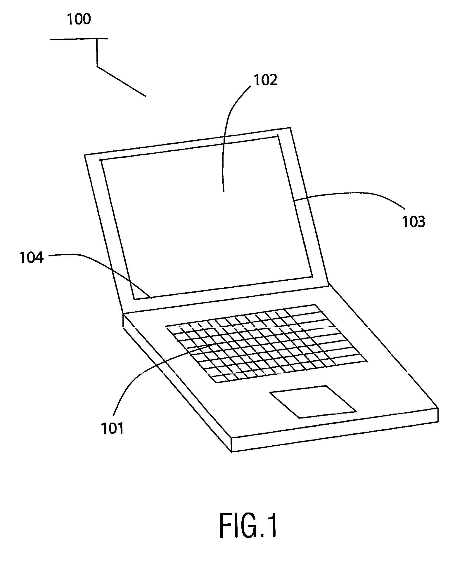
[0037]FIG. 1 shows a display device 100 in the form of a laptop arranged with a keyboard 101 and an LCD flat screen 102, in which display device the present invention advantageously can be applied. The coordinate detection system according to the present invention comprising a light guiding layer and light detecting means can be arranged in the display device in a number of different ways, as will be described. For example, the layer can be arranged in the interior of the display device, or preferably, attached to the exterior of the screen. The light detecting means can be arranged at two of the edges 103, 104 of the screen, but can also be arranged in a substrate of the display device, thereby placing the light detecting means in the interior of the display device.

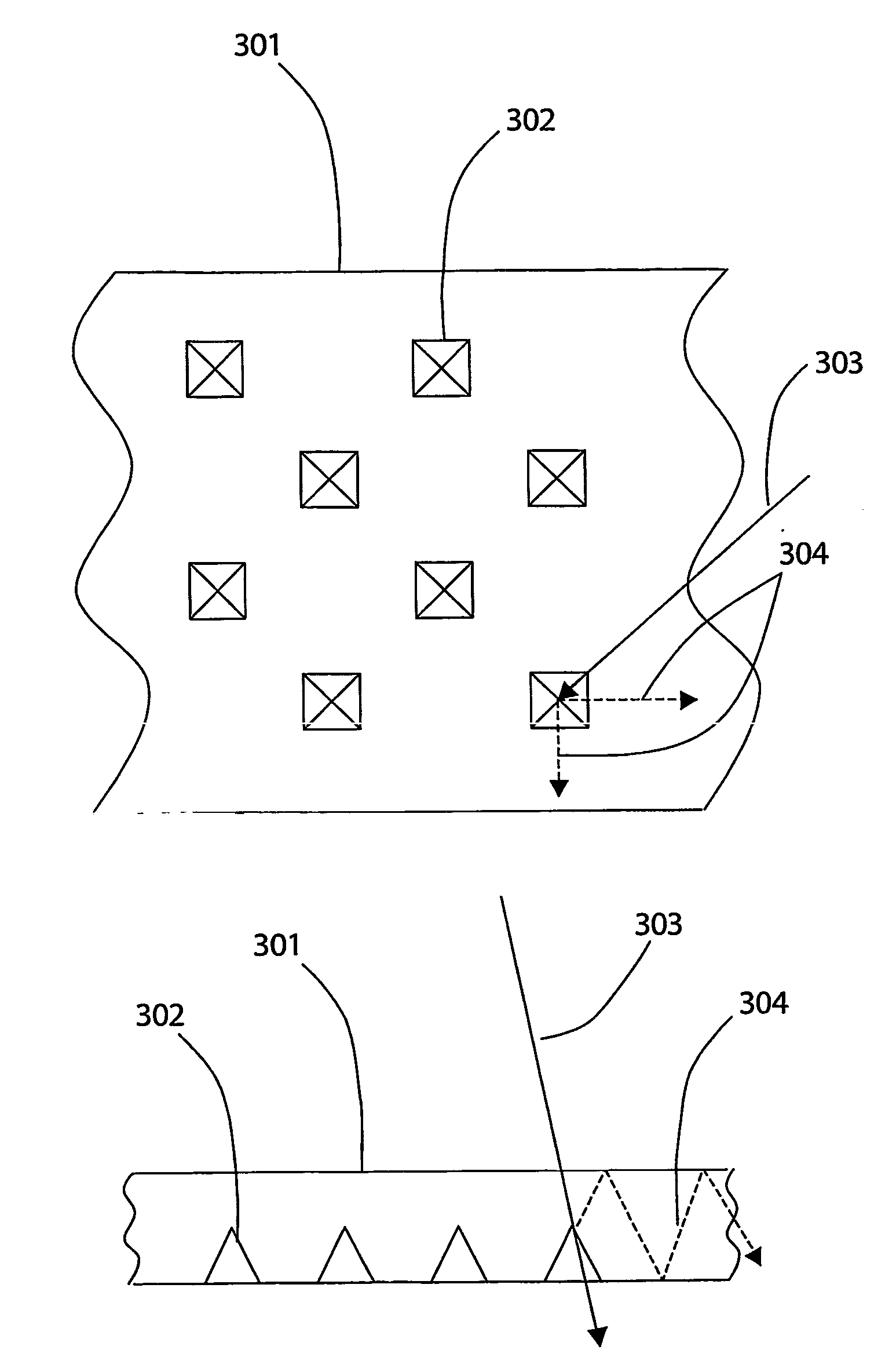
[0038]FIG. 2 shows a schematic front view of a display device screen 201, on which a light guiding layer 202 is arranged by means of adhesive. At two of the edges of the layer, light detecting means 203 in the form of e...


PUM

PropertyMeasurementUnit
top angleaaaaaaaaaa
structureaaaaaaaaaa
volumeaaaaaaaaaa

Abstract

The present invention relates to an apparatus for detecting an input position on a screen of a display monitor. The apparatus comprises a light guiding layer (301) having an optical structure such that a fraction (304) of the light (303) incident on the layer (301) from the apparatus' exterior is confined in the layer (301). The incident light (303) is emitted by a remote input device, operable by a user, for interacting with the apparatus. The remote input device is, for example, a laser pointer (205). Light detecting means (803) in the apparatus detects the light (304) confined in the layer (301). It is thus possible to determine the input position (206) where the light (207) from the input device enters the layer (301).

Description

FIELD OF THE INVENTION [0001] The present invention relates to a user input apparatus for detecting an input position relative to the apparatus as a result of user interaction with the apparatus. The apparatus preferably comprises a display monitor. BACKGROUND ART [0002] To improve the interactivity between users and computers, touch screen displays have been introduced for multimedia information kiosks, educational centers, vending machines, video games, PCs, etc. A touch screen display is a display screen which can be affected by physical contact, allowing a user to interact with the computer by touching icons, pictures, words or other visual objects on the computer screen. Touching, i.e. establishment of physical contact with the screen, is usually done with a finger, a pen to prevent the screen from becoming dirty and stained, or some other appropriate stylus or pointing device. [0003] Sometimes physical contact for providing straight forward interactivity is not the best option...

Claims


Application Information

Patent Timeline
Patent Type & Authority Applications(United States)
IPC IPC(8): G09G5/00F21V8/00G02F1/133G06F3/038G06F3/041G06F3/042
CPCG02B6/0038G02F1/13338G06F2203/04109G06F3/042G06F3/0386G02B6/00
Inventor GIRALDO, ANDREADESTURA, GALILEO JUNE ADEVACORNELISSEN, HUGO JOHANJAK, MARTIN JACOBUS JOHAN
Owner KONINKLIJKE PHILIPS ELECTRONICS NV
Why Eureka
Try Eureka