Liquid-jet head and method of producing the same and liquid injection device

a liquid-jet head and liquid-jet technology, applied in printing and other directions, can solve the problems of difficult piezoelectric elements in high density, complicated fabrication process, and formation of piezoelectric elements, and achieve the effect of easy formation

Active Publication Date: 2006-12-28
SEIKO EPSON CORP
View PDF17 Cites 53 Cited by
  • Summary
  • Abstract
  • Description
  • Claims
  • Application Information

AI Technical Summary

Benefits of technology

[0079] In the thirty-fourth aspect, the moisture permeable portion can be easily formed without making the production process complicated.

Problems solved by technology

However, the former recording head has a drawback in that a fabrication process is complicated; specifically, fabrication involves a difficult process of dividing the piezoelectric element into comb-tooth-like segments at intervals corresponding to those at which nozzle orifices are arranged, as well as a process of fixing the piezoelectric segments in such a manner as to be aligned with corresponding pressure generation chambers.
However, the latter recording head has a drawback in that a piezoelectric element requires a certain area in order to utilize flexural vibration, thus involving difficulty in arranging piezoelectric elements in high density.
Piezoelectric elements formed in such a manner have a problem in that they are easily broken because of, for example, characteristics of the external environment such as moisture.
However, even in the case where piezoelectric elements are sealed in this manner, there arises a problem in that when water enters the piezoelectric-element-holding portion through a bonding portion between the sealing substrate and the channel substrate, the quantity of moisture within the piezoelectric-element-holding portion gradually increases, and finally, the piezoelectric elements are broken because of the moisture.
Therefore, breakage of piezoelectric elements due to water cannot be prevented completely.
However, since the stress produced in the protective film formed of the above-described material is typically tensile stress, when piezoelectric elements are covered with such a protective film, there arises a problem in that compression force acts on the piezoelectric elements (piezoelectric layer), and the amount of displacement of the vibration plate caused through drive of a piezoelectric element drops.
Further, the protective film formed of an organic material cannot prevent permeation of water unless it has a considerably large thickness.
However, the large thickness may become an influential factor which hinders drive of the piezoelectric elements.
The above-described problems arise not only in ink-jet recording heads which discharge ink droplets, but also in liquid-jet heads which discharge droplets of liquid other than ink.

Method used


Image

  • Liquid-jet head and method of producing the same and liquid injection device
  • Liquid-jet head and method of producing the same and liquid injection device
  • Liquid-jet head and method of producing the same and liquid injection device

Examples


embodiment 1

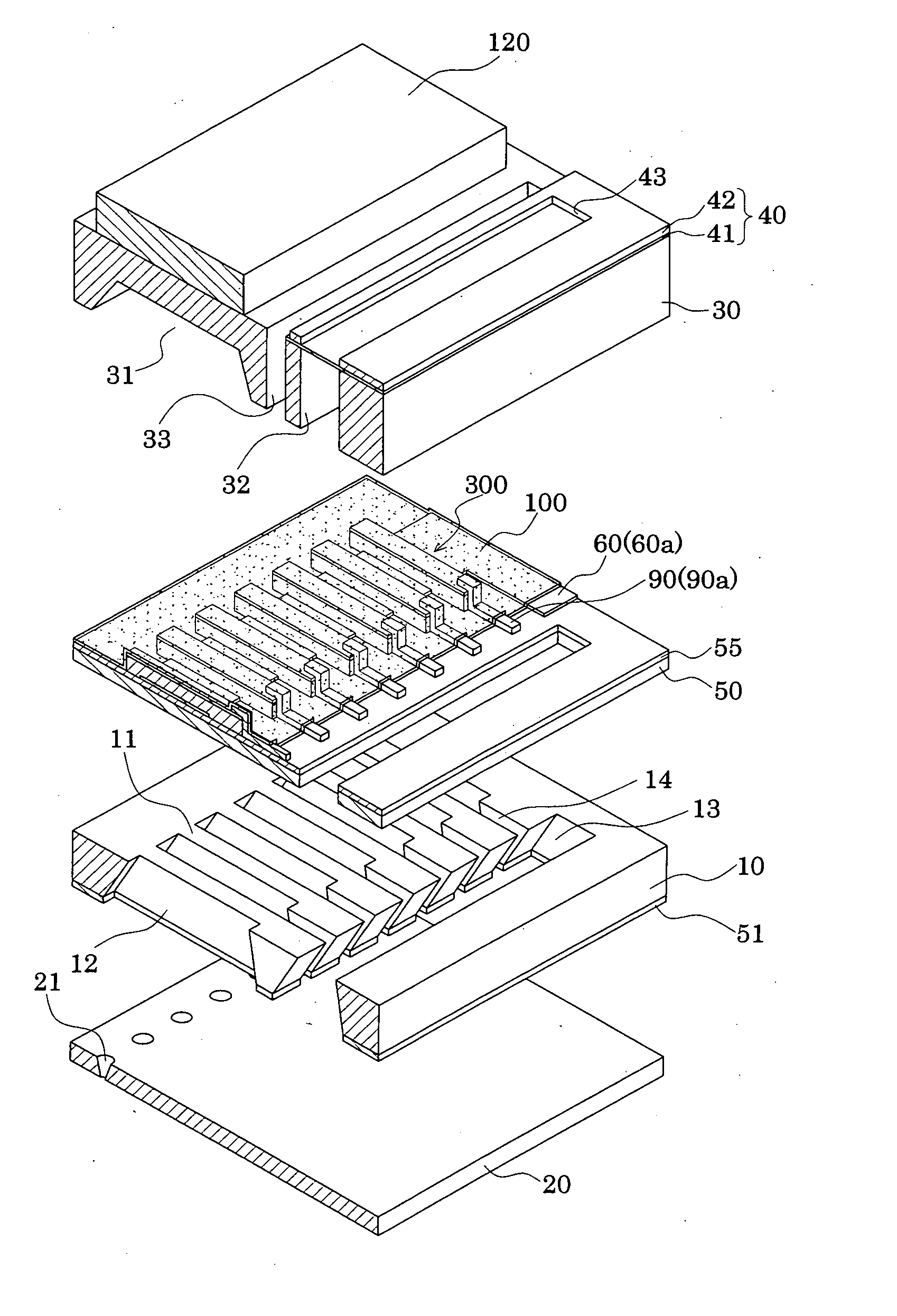
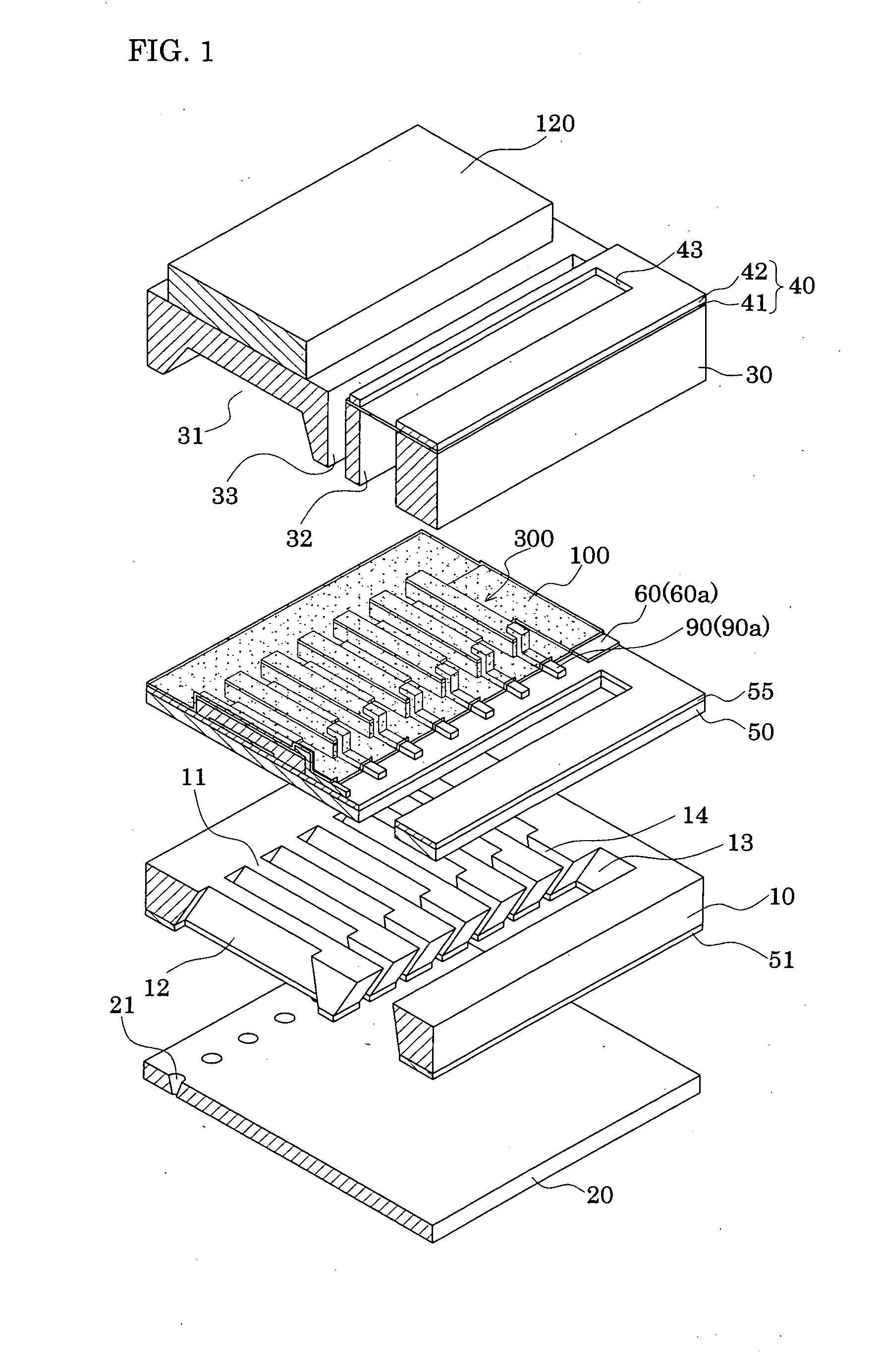
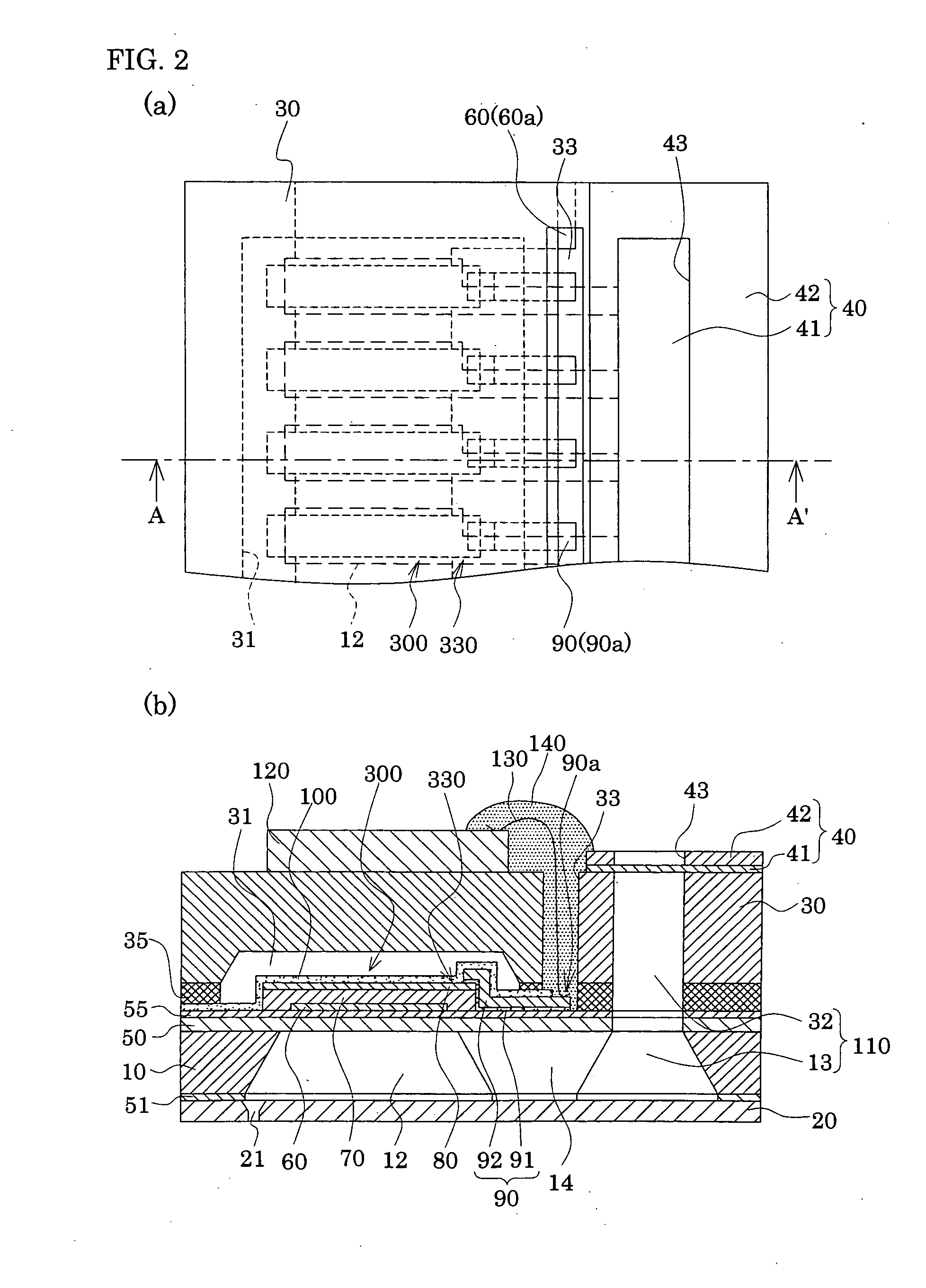
[0105]FIG. 1 is an exploded perspective view of an ink-jet recording head according to Embodiment 1 of the present invention. FIG. 2 shows plan and sectional views of the recording head of FIG. 1. As shown in these drawings, in the present embodiment a channel substrate 10 is formed of a monocrystalline silicon substrate which has a crystal face orientation of (110). An elastic film 50 is formed beforehand on one side of the channel substrate 10 by means of thermal oxidation. The elastic film 50 is formed of silicon dioxide and has a thickness of 0.5 μm to 2 μm. In the channel substrate 10, a plurality of pressure generation chambers 12 are provided in proximity, in a row arrangement in their width direction. A communication section 13 is formed in the channel substrate 10 in a region located longitudinally outside the pressure generation chambers 12. The communication section 13 communicates with the pressure generation chambers 12 via corresponding ink supply channels 14 provided ...

example 1

[0131] An ink-jet recording head of Example 1 was manufactured in such a manner that an insulating film of aluminum oxide, which is an inorganic insulating material, was formed to have a thickness of about 50 nm and to cover the pattern regions of the respective layers of the piezoelectric elements and the upper-electrode lead electrodes, except for the connection portions of the lower electrode film and the connection portions of the upper-electrode lead electrodes.

example 2

[0132] An ink-jet recording head of Example 2 was manufactured to have the same structure as that of Example 1, except that the insulating film was formed to have a thickness of about 100 nm.


PUM


Abstract

There are provided a liquid-jet head which can reliably prevent breakage of piezoelectric elements over a long period of time, and a method for manufacturing the liquid-jet head, as well as a liquid-jet apparatus. Further, there are provided a liquid-jet head which can effectively prevent a drop in the amount of displacement of a vibration plate caused through drive of a piezoelectric element, and a method for manufacturing the liquid-jet head, as well as a liquid-jet apparatus.
A liquid-jet head includes a channel substrate 10 which has pressure generation chambers 12 formed therein and communicating nozzle orifices for discharging liquid droplets, and piezoelectric elements 300 each of which is composed of a lower electrode 60, a piezoelectric layer 70, and an upper electrode 80 and which are disposed on one surface of the channel substrate 10 via a vibration plate, wherein at least pattern regions of the respective layers which constitute the piezoelectric elements 300 are covered with an insulating film 100 formed of an inorganic insulating material.

Description

TECHNICAL FIELD [0001] The present invention relates to a liquid-jet head and to a method for manufacturing the liquid-jet head, as well as to a liquid-jet apparatus. More particularly, the invention relates to an ink-jet recording head in which a vibration plate partially constitutes pressure generation chambers communicating with corresponding nozzle orifices for discharging ink droplets, piezoelectric elements are formed on the surface of the vibration plate, and displacement of the piezoelectric elements causes discharge of ink droplets, and to a method for manufacturing the ink-jet recording head, as well as to an ink-jet recording apparatus. BACKGROUND ART [0002] Ink-jet recording heads which have been put into practical use include two kinds in which a vibration plate partially constitutes pressure generation chambers communicating with corresponding nozzle orifices for discharging ink droplets, and piezoelectric elements cause the vibration plate to be deformed so as to appl...

Claims


Application Information

Patent Timeline
Patent Type & Authority Applications(United States)
IPC IPC(8): B41J2/045B41J2/14B41J2/16
CPCB41J2/14233B41J2/161B41J2/1623B41J2/1628B41J2/1629B41J2002/14491B41J2/1635B41J2/1642B41J2002/14241B41J2002/14419B41J2/1632B41J2/045B41J2/16B41J2/14
Inventor SHIMADA, MASATOYAZAKI, SHIRONISHIWAKI, TSUTOMUTSUDA, AKIHITOYAMADA, MASATAKA
Owner SEIKO EPSON CORP
Why Eureka
Try Eureka