
Doherty amplifier and transmitter using mixer

a doherty amplifier and mixer technology, applied in the direction of polarisation/directional diversity, baseband system details, pulse techniques, etc., can solve the problems of inability to manufacture monotype chips, inability to realize the doherty structure as a single chip, and inability to manufacture 90° couplers b>40/b> through the cmos process, etc., to achieve the effect of high frequency noise and high frequency noise components

Active Publication Date: 2006-12-28
SAMSUNG ELECTRONICS CO LTD
View PDF29 Cites 17 Cited by
  • Summary
  • Abstract
  • Description
  • Claims
  • Application Information

AI Technical Summary

Benefits of technology

[0036] According to yet another aspect of the present invention, there is provided a direct conversion transmitter including: first and second digital-to-analog converters respectively converting input I-channel and Q-channel digital signals into I-channel and Q-channel analog signals; a local oscillator signal generator outputting an in-phase local oscillator signal, a quadrature-phase local oscillator signal, and an inverted phase local oscillator signal; first and second mixers mixing the I-channel analog signal with the in-phase and quadrature-phase local oscillator signals to output I-channel in-phase and quadrature-phase high frequency signals; third and fourth mixers mixing the Q-channel analog signal with the quadrature-phase and inverted phase local oscillator signals to output Q-channel in-phase and quadrature-phase high frequency signals; a first main amplifier and a first auxiliary amplifier respectively amplifying the I-channel in-phase high frequency signal output from the first mixer and the I-channel quadrature-phase high...

Problems solved by technology

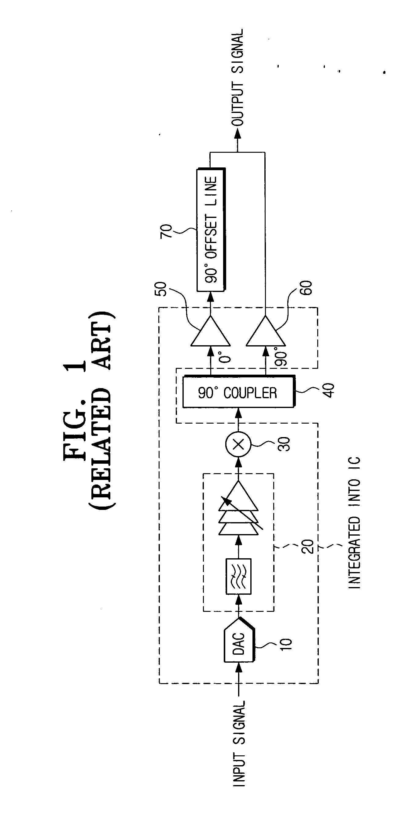
However, a 90° coupler inappropriate for integrated circuit (IC) integration is required to be used in a transmitter using a Doherty structure.
Thus, it is difficult to manufacture monotype chips.
However, the 90° coupler 40 cannot be manufactured through the CMOS process due to its size.
Thus, the Doherty structure cannot be realized as a single chip RFIC.

Method used


Image

  • Doherty amplifier and transmitter using mixer
  • Doherty amplifier and transmitter using mixer
  • Doherty amplifier and transmitter using mixer

Examples


Embodiment Construction

[0045] Certain exemplary embodiments of the present invention will be described in greater detail with reference to the accompanying drawings.

[0046] In the following description, the same drawing reference numerals are used for the same elements throughout the drawings. The matters defined in the description are only provided to assist understanding of the invention. However, the present invention can be carried out in different manners from those disclosed herein. Also, well-known functions or constructions are not described in detail since they would obscure the invention in unnecessary detail.

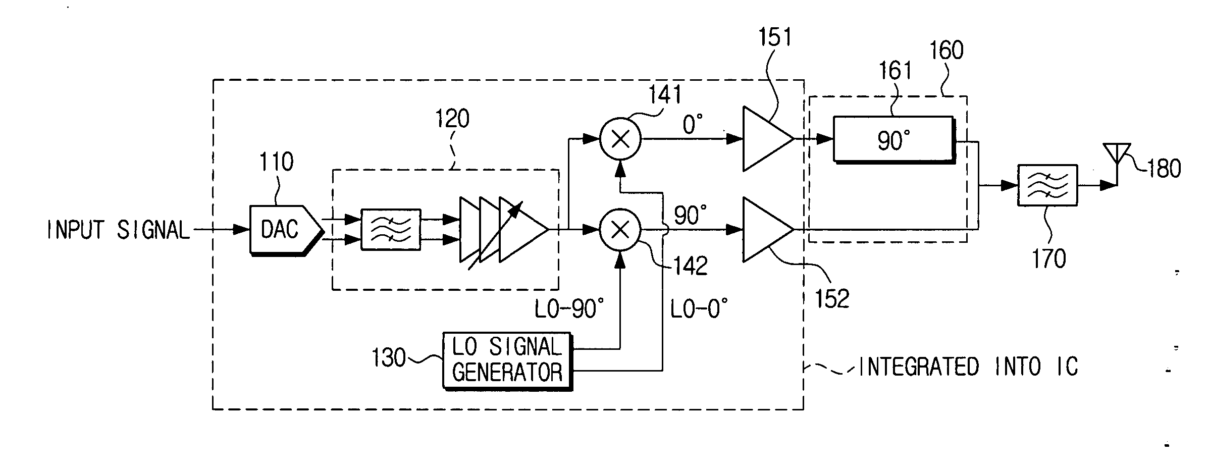
[0047]FIG. 3 is a block diagram of a transmitter according to an exemplary embodiment of the present invention. Referring to FIG. 3, the transmitter includes a DAC 110, a base band analog filter 120, a local oscillator (LO) signal generator 130, first and second mixers 141 and 142, a main amplifier 151, and a peak amplifier 152, a phase difference compensator 160, a band selection filter 1...


PUM


Abstract

A transmitter and a signal amplifier are provided. The signal amplifier includes a digital-to-analog converter converting an input digital signal into an analog signal, a local oscillator signal generator outputting in-phase and quadrature-phase oscillator signals, a first mixer mixing the analog signal with the in-phase local oscillator signal to output an in-phase high frequency signal, a second mixer mixing the analog signal with the quadrature-phase local oscillator signal to output a quadrature-phase high frequency signal, a main amplifier amplifying the in-phase high frequency signal output from the first mixer, and an auxiliary amplifier amplifying the quadrature-phase high frequency signal output from the second mixer.

Description

CROSS-REFERENCE TO RELATED APPLICATIONS [0001] This application claims priority from Korean Patent Application No. 10-2005-0055841 filed Jun. 27, 2005 in the Korean Intellectual Property Office, the disclosure of which is incorporated herein by reference. BACKGROUND OF THE INVENTION [0002] 1. Field of the Invention [0003] Apparatuses and methods consistent with the present invention relate to a transmitter and a signal amplifier, and more particularly, to a transmitter and a signal amplifier using a Doherty structure without a 90° coupler. [0004] 2. Description of the Related Art [0005] Complementary metal-oxide semiconductor (CMOS) technology contributes to reducing sizes of chips so as to be advantageous to integration and thus is most suitable for realizing system on a chip (SoC). A radio frequency (RF) performance becomes higher with the reduction in the sizes of the chips. However, a 90° coupler inappropriate for integrated circuit (IC) integration is required to be used in a t...

Claims


Application Information

Patent Timeline
IPC IPC(8): H04B7/00
CPCH04B2001/0408H04B1/04H03F3/24H03F1/07H04B1/02
Inventor PARK, JIN-SOOKIM, DO-HYUNGBURM, JIN-WOOKLEE, SEONG-SOOLEE, HEUNG-BAE
Owner SAMSUNG ELECTRONICS CO LTD
Learn More