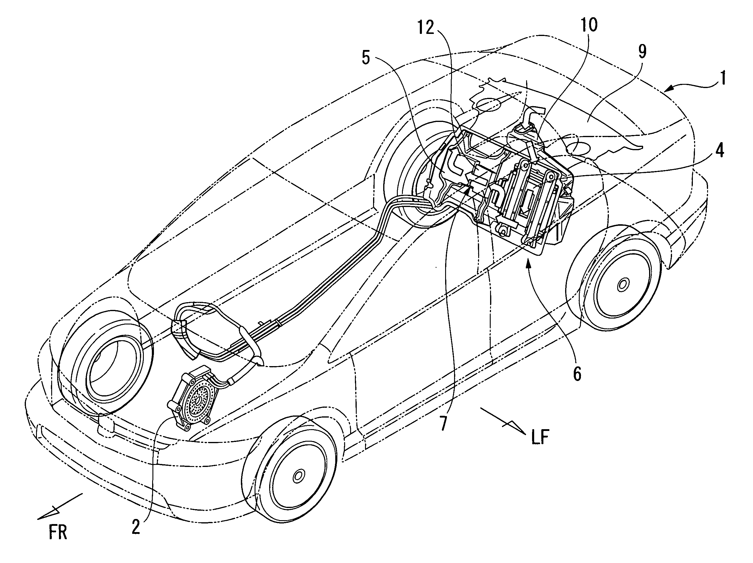
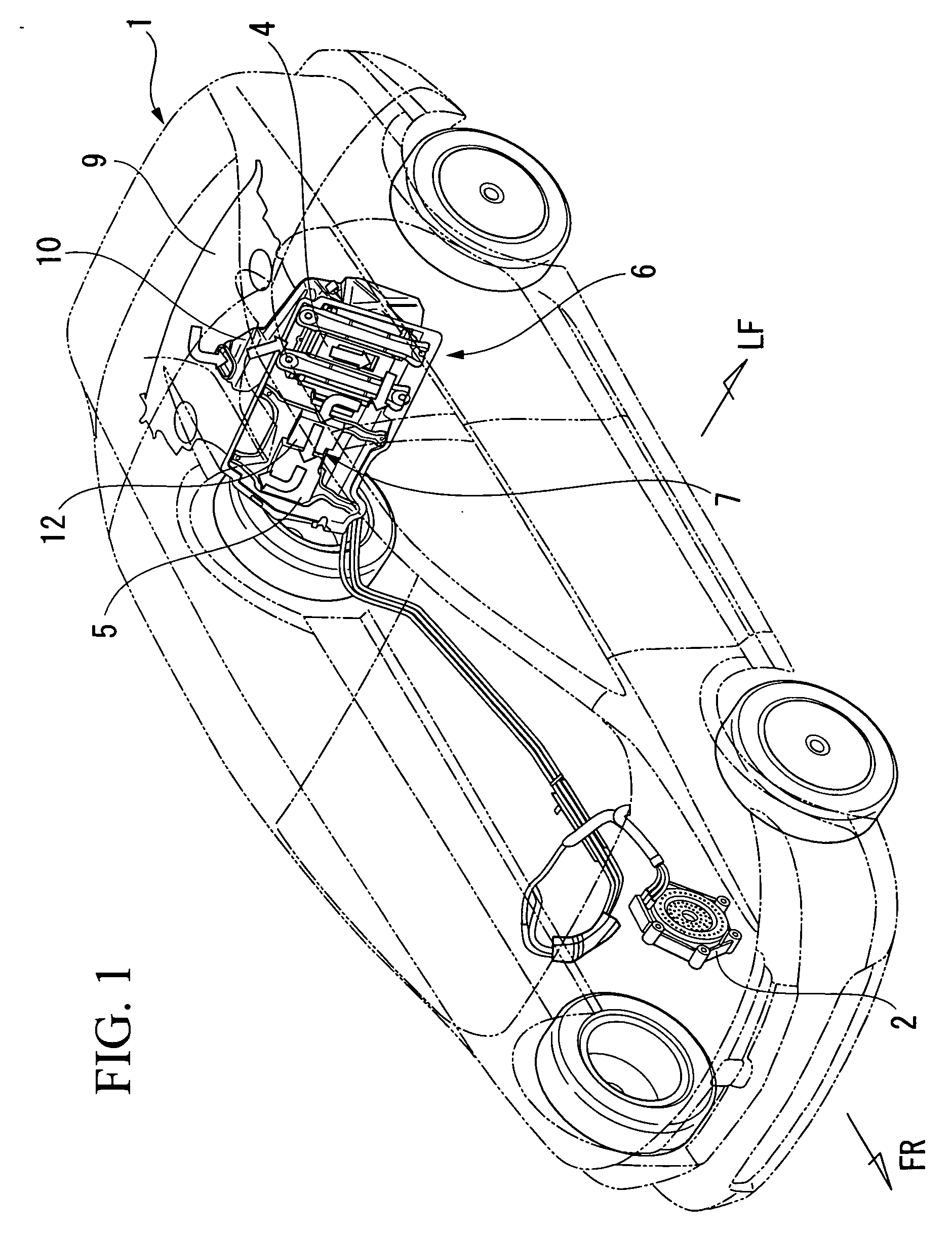
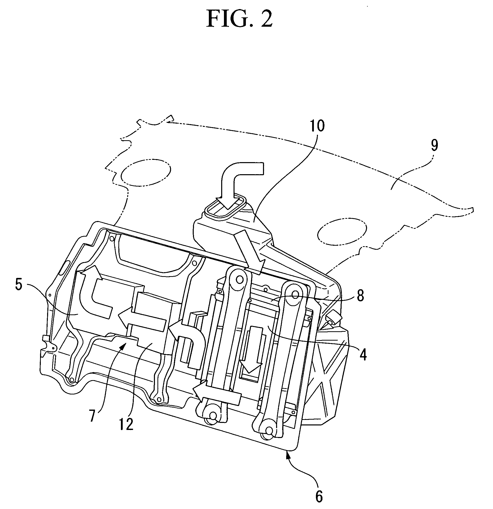
Cooling apparatus for vehicle electrical packaging unit

a technology for electrical packaging units and cooling apparatuses, which is applied in the direction of electric devices, light and heating apparatuses, battery/fuel cell control arrangements, etc. it can solve the problems of space-saving and concentrated arrangement of high-voltage electrical devices, heat radiating fins 111/b>, and the formation of passages. , to achieve the effect of compact apparatus, easy and independent attachment, and reduced manufacturing costs

Inactive Publication Date: 2007-01-04
HONDA MOTOR CO LTD
View PDF8 Cites 36 Cited by
  • Summary
  • Abstract
  • Description
  • Claims
  • Application Information

AI Technical Summary

Benefits of technology

[0009] Thus, it is an object of the present invention to provide a cooling apparatus for a vehicle electrical packaging unit that enables a reduction in fabrication cost and increased compactness by using parts that are easily fabricated, and by realizing a space-saving and concentrated arrangement of the high voltage electrical devices, including, for example, an inverter for a vehicle drive motor and a DC-DC converter for a vehicle control power source.

Problems solved by technology

However, in this conventional cooling apparatus, the heat sink case 109 is integrally formed by die casting or the like, and thus there are disadvantages in that the fabrication for forming the passage 110 and the heat radiating fins 111 therein is difficult, and a space-saving and concentrated arrangement of the high voltage electrical devices 107 and 108 in the pre-molded heat sink case 109 is difficult.

Method used


Image

  • Cooling apparatus for vehicle electrical packaging unit
  • Cooling apparatus for vehicle electrical packaging unit
  • Cooling apparatus for vehicle electrical packaging unit

Examples


second embodiment

[0068]FIG. 11 shows a second embodiment.

[0069] An electrical packaging unit 207 of this embodiment is used in a vehicle provided with two vehicle drive motors, and is provided with two PDUs 41 and 42 having invertors for each motor, a DC-DC converter 43 for the vehicle control power source, and the electrical power converter 44 for driving the electrical accessories. The PDUs 41 and 42, the DC-DC converter 43, and the electrical power converter 44 are respectively mounted on heat radiating plates 45 to 46, which have heat radiating fins, and the two heat radiating plates 45 and 46 of the PDUs 41 and 42 are adjacent to each other. The heat radiating plate 47 of the DC-DC converter 43 and the heat radiating plate 48 of the electrical power converter 44 are respectively disposed adjacent to positions opposed to the heat radiating plates 45 and 46 of the PDUs 41 and 42, that is, the heat radiating plate 47 for the DC-DC converter 43 is on the upstream side, and the heat radiating plate...

third embodiment

[0070]FIG. 12 shows a third embodiment.

[0071] An electrical packaging unit 407 of this embodiment is provided with one PDU 61 having one inverter for a vehicle drive motor, a DC-DC converter 63 for a vehicle control power source, and two electrical power converters 62 and 64 for driving electrical accessories. The PDU 61, the electrical power converter 62, the DC-DC converter 63, and the electrical power converter 64 are respectively mounted on heat radiating plates 65 to 68, and the heat radiating plate 66 of the electrical power converter 62 is disposed adjacent on the downstream side of the heat radiating plate 65 of the PDU 61. Each of the heat radiating plates 67 and 68 of the DC-DC converter 63 and the electrical power converter 64 are disposed adjacent to each other at positions opposed to the heat radiating plate 65 of the PDU 61 and the heat radiating plate 66 of the electrical power converter 62.

fourth embodiment

[0072]FIG. 13 shows a fourth embodiment.

[0073] An electrical packaging unit 507 of this embodiment is provided with one PDU 71 having an inverter for a vehicle drive motor, a step-up DC-DC converter 72, a step-down DC-DC converter 73 for the vehicle control power source, and an electrical power converter 74 for driving the electrical accessories. The PDU 71, the DC-DC converters 72 and 73, and the electrical power converter 74 are respectively mounted on heat radiating plates 75 to 78, and disposed such that the heat radiating plate 76 of the DC-DC converter 72 is adjacent to the downstream side of the heat radiating plate 75 of the PDU 71. Each of the heat radiating plates 77 and 78 for the DC-DC converter 73 and the electrical power converter 74 are disposed adjacent to the positions opposed to the heat radiating plates 75 and 76 such that the heat radiating plate 77 of the DC-DC converter 73 is on the upstream side of the heat radiating plate 78 of the electrical power converter...


PUM


Abstract

A cooling apparatus for a vehicle electrical packaging unit that includes an inverter for a vehicle drive motor, a DC-DC converter for a vehicle control power source, and an electrical power converter for driving the electrical accessories, and cools them by heat exchange with cooling air. The cooling apparatus includes a first heat radiating plate for the inverter, a second heat radiating plate for the DC-DC converter, a third heat radiating plate for the electrical power converter, and connecting members that respectively connect the first heat radiating plate to the second heat radiating plate and the first heat radiating plate to the third heat radiating plate. Heat radiating fins of the first to third heat radiating plates are enclosed by the first heat radiating plate, second heat radiating plate, the third heat radiating plate, and the connecting members to form an air passage through which the cooling air passes.

Description

BACKGROUND OF THE INVENTION [0001] 1. Field of the Invention [0002] The present invention relates to a cooling apparatus for a vehicle electrical packaging unit that includes an inverter for driving a vehicle driving motor, a DC-DC converter for a vehicle control electric power source, an electrical power converter for driving electrical accessories, and other high voltage electrical devices, and in particular, relates to a cooling apparatus for a vehicle electrical packaging unit that cools a plurality of high voltage electrical devices by heat exchange with cooling air. [0003] Priority is claimed on Japanese Patent Application No. 2005-194733, filed Jul. 4, 2005, the content of which is incorporated herein by reference. [0004] 2. Description of Related Art [0005] In electrical automobiles and so-called hybrid vehicles, high voltage electrical devices, such as high voltage electrical devices include an inverter for a vehicle drive motor, a DC-DC converter for a vehicle control elec...

Claims


Application Information

Patent Timeline
Patent Type & Authority Applications(United States)
IPC IPC(8): F03H1/00
CPCB60H1/00428B60H1/244H05K7/20918B60H2001/00614B60H1/248B60H2001/003B60L1/003B60L3/003B60L7/14B60L50/16B60L50/66B60L58/20B60L58/21B60L2210/10B60L2210/40B60L2240/36B60L2240/547B60L2240/549Y02T10/70Y02T10/7072Y02T10/72Y02T10/88
Inventor OTSUKA, HIROSHIYAMAGUCHI, HIROOFUKAZU, TOMOHIRONAKATSU, MASANOBUOGIHARA, YASUSHI
Owner HONDA MOTOR CO LTD
Why Eureka
Try Eureka