Method for operating a pulsed arc source

a pulsed arc and source technology, applied in the direction of electrodes, diaphragms, ion implantation coatings, etc., can solve the problems of cathode, high production cost, and high cost of operation,

Active Publication Date: 2007-01-04
OERLIKON SURFACE SOLUTIONS AG PFAFFIKON
View PDF21 Cites 82 Cited by
  • Summary
  • Abstract
  • Description
  • Claims
  • Application Information

AI Technical Summary

Problems solved by technology

However, the arc source described, employing a target body with a very complex geometry, is expensive to make especially when difficult-to-cut cathode materials are used, and its operation is costly.
U.S. Pat. No. 6,361,663 describes an arc source with a cathode of an electrically conductive material that is pulsed, or pulsed in modulated fashion, with peak currents of up to 5 kA and a base current for instance of 100 A. That source as well, configured with a magnetic tunnel and an anode that is completely surrounded by the cathode, is expensive to produce and to operate.
What these processes have in common is that the use of reactive gases causes the latter to react with the vaporized material or materials, which quickly leads to the formation of an insulating layer, requiring special measures that prevent contamination of the active target or anode surface as well as the formation of undesirable droplets.
While the positive temperature gradient of semiconductors provides sufficiently good conductivity in the area of the arc spot to allow the arc to burn, the concomitant, increased tendency of the arc to stick usually leads to a higher level of spattering than would be the case with conductive metal target surfaces.
For example, as mentioned above, the source can be positioned outside the optical connecting path to the target surface, which, however, drastically reduces the yield of the target material and the deposition rate.
The common denominator for all these methods, and their equally well-known combinations, is significant additional technical complexity and / or a substantial reduction of the deposition rate.
And yet, if an insulating layer forms on the target surface, even these measures have not so far produced a stable process.

Method used


Image

  • Method for operating a pulsed arc source
  • Method for operating a pulsed arc source
  • Method for operating a pulsed arc source

Examples


example # 1

EXAMPLE #1

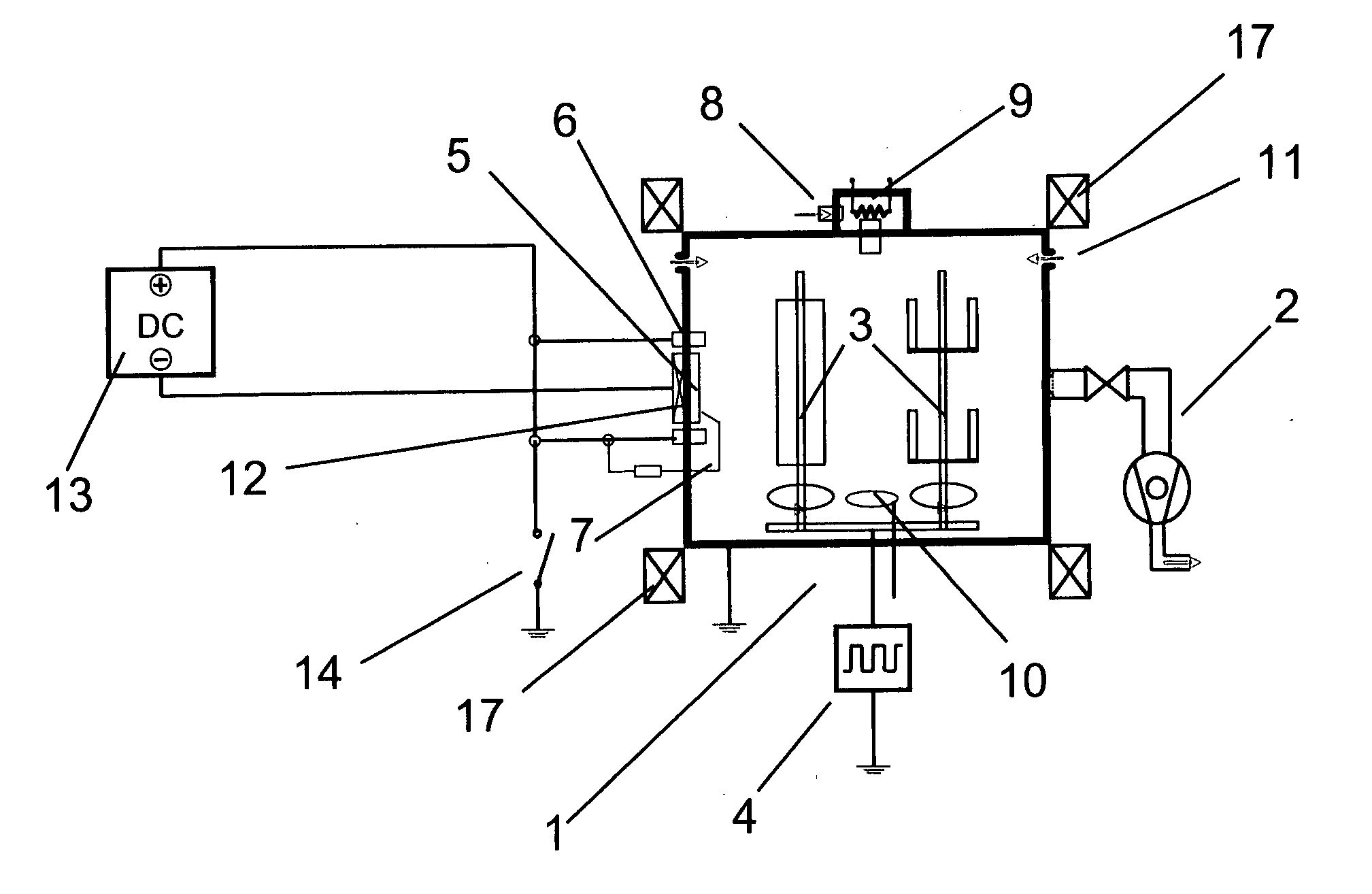
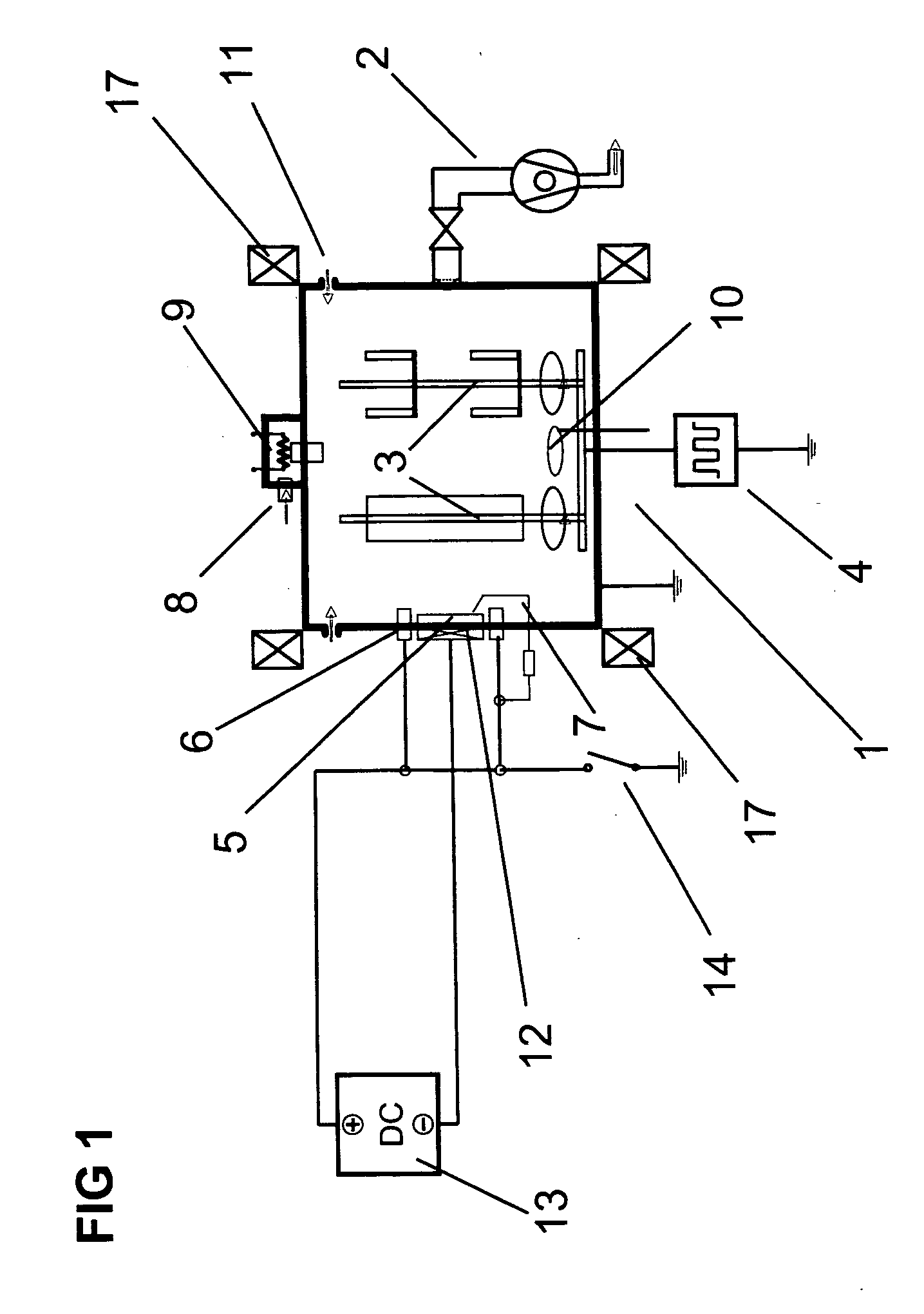
[0051] After placing the work pieces in the appropriate double- or triple-rotatable holders and the holders in the vacuum processing system, the processing chamber was pumped down to a pressure of about 10−4.

[0052] For setting the process temperature a low-voltage arc (LVA) plasma, aided by radiation heaters, was ignited between a cathode chamber with a hot cathode, separated by a baffle, and the anodic work pieces in an argon-hydrogen atmosphere.

[0053] The heating parameters were selected as follows:

Discharge current, LVA150 AArgon flow50 ccm / sHydrogen flow300 ccm / sProcess pressure1.4 × 10−2 mbarSubstrate temperatureapprox. 500° C.Process duration45 min.

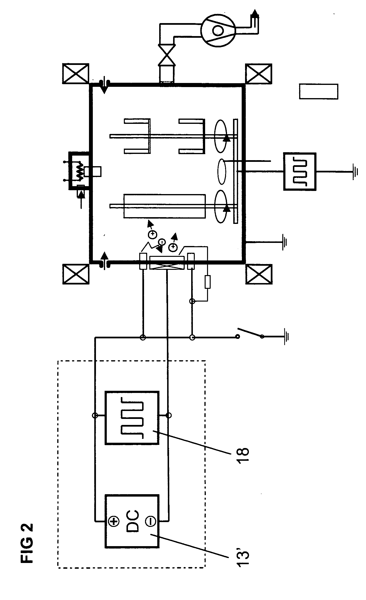
[0054] Those skilled in the art are familiar with alternative parameters. The substrates were preferably used as anodes for the low-voltage arc and also preferably pulsed in a unipolar or bipolar mode.

[0055] As the next procedural step the etching was started. To that end the low-voltage arc was operated between the f...


PUM

PropertyMeasurementUnit
currentaaaaaaaaaa
currentaaaaaaaaaa
currentaaaaaaaaaa

Abstract

This invention relates to an arc-based method for the deposition of insulating layers and to an arc-based method for low-temperature coating processes, in which an electric arc discharge, ignited and applied on the surface of a target in an arc source, is simultaneously fed a direct current and a pulsed or alternating current.
The invention further relates to an arc source in which the target is connected to a power supply unit that encompasses either a minimum of one pulsed high-current power supply 18, 18′ and an additional power supply 13′, 18″, or a power supply 21, 21′, 22 designed with switchable combinatorial circuitry.

Description

TECHNICAL DOMAIN [0001] This invention relates to a method for operating an arc source per preamble and main concept of claim 1, 8 and 9, respectively, and to an arc source as specified in claim 34, 43 and 45, respectively. PRIOR ART [0002] Prior art has employed pulsed arc sources for some time. WO 02 / 070776, for example, describes in a very general way the use of a pulsed arc for cutting super-hard TiSiN layers, among others. [0003] WO 03 / 057939 describes an arc source in which the arc is ignited via a pulsed high-voltage power supply and the arc is then fed by a pulsed high-current power supply. The arc is operated in discontinuous fashion. The base materials are metallic conductive cathodes, conductive alloys and, additionally, carbon or, alternatively, vaporizable semiconductors. However, the arc source described, employing a target body with a very complex geometry, is expensive to make especially when difficult-to-cut cathode materials are used, and its operation is costly. [...

Claims


Application Information

Patent Timeline
Patent Type & Authority Applications(United States)
IPC IPC(8): C23C14/32C23C14/00
CPCC23C14/024C23C14/0641C23C14/08C23C14/081C23C14/083F05D2230/313F01D5/288H01J37/32055H01J37/34H01J37/3444C23C14/325C23C14/00C23C14/28C23C14/32H01J37/32
Inventor RAMM, JURGENGSTOEHL, OLIVERWIDRIG, BENOLENDI, DANIEL
Owner OERLIKON SURFACE SOLUTIONS AG PFAFFIKON
Why Eureka
Try Eureka