
Organic compound hydrogenation apparatus and method for hydrogenating organic compound

a technology of organic compound and hydrogenation apparatus, which is applied in the direction of electrolytic organic production, electrode coating, separation process, etc., can solve the problems of insufficient hydrogenation efficiency of organic compound, high inefficiency, etc., and achieve the effect of enhancing the efficiency of organic compound hydrogenation

Inactive Publication Date: 2007-01-04
IDEMITSU KOSAN CO LTD
View PDF4 Cites 10 Cited by
  • Summary
  • Abstract
  • Description
  • Claims
  • Application Information

AI Technical Summary

Benefits of technology

[0008] An object of the present invention is to provide a method for hydrogenating an organic compound and an organic compound hydrogenation apparatus which are capable of enhancing efficiency of hydrogenation of the organic compound.
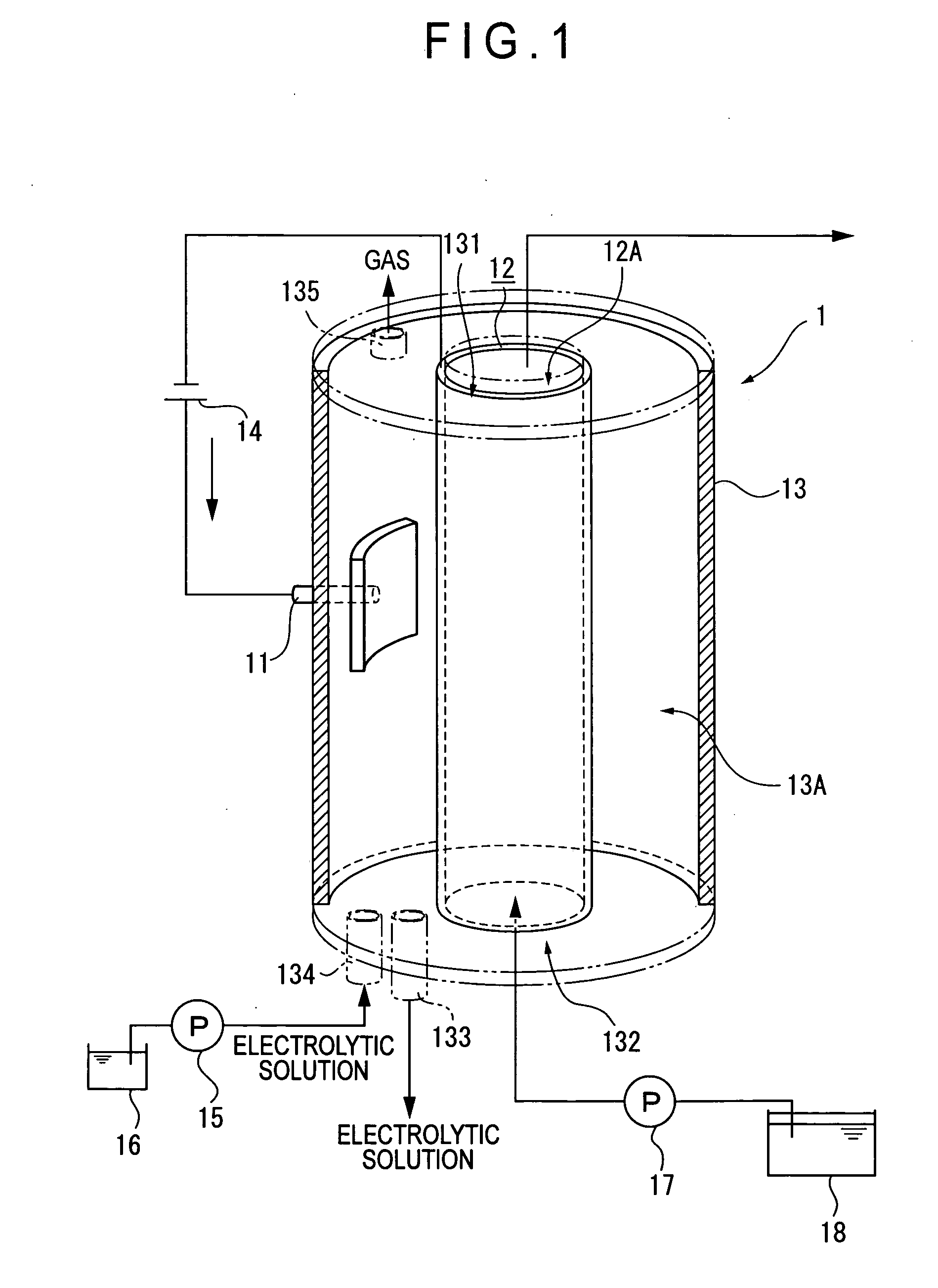
[0026] According to the present invention described above, since the cathode is made of a material including a hydrogen storage material, and is arranged as a tubular member so that the organic compound as an object to be treated circulates inside, conducting electrolysis in a reaction cell filled with an electrolytic solution results in generation of hydrogen on the outer surface of the cathode, and the generated hydrogen is absorbed in the tube wall of the cathode. Then, since the organic compound circulating inside the tube is in a state surrounded by the tube wall of the cathode, it can easily contact with the tube wall in which hydrogen is absorbed, so that a contact area effective for hydrogenation of organic compounds becomes larger as compared to that of a conventional cathode having a division plate-like shape or the like, thereby enhancing the efficiency of hydrogenation of the organic compound.
[0032] With the arrangement, since the hydrogen storage material itself acts as a catalyst upon hydrogenation reaction of the organic compound, reaction rate of the hydrogenation reaction can be enhanced further.
[0035] With the arrangement, since the hydrogen storage material has a large surface area, which increases an area where the organic compound contacts effectively with hydrogen, reaction rate of the hydrogenation reaction can further be enhanced.
[0038] According to the present invention described above, by electrolyzing the electrolytic solution existing between the anode and cathode, while circulating the organic compound as an object to be treated inside the tube of the cathode, hydrogen is generated on the outer surface of the cathode and the generated hydrogen is absorbed in the tube wall of the cathode. Further, since the circulating organic compound is in a state surrounded by the tube wall of the cathode, it can easily contact with the tube wall in which hydrogen has been absorbed, and the contact area effective for hydrogenation of the organic compound becomes larger as compared to the conventional division plate-like cathode and the like, thereby enhancing the efficiency of hydrogenation of the organic compound.

Problems solved by technology

However, in the hydrogenation reaction which uses palladium or hydrogen storage metal alloy, since amount of hydrogen that can be absorbed thereinto is limited, there is such a defect that the stored hydrogen is consumed along with progress of the reaction and further reaction does not proceed, thereby allowing only so-called a batch system reaction to proceed.
Thus, although there is no problem in a laboratory scale operation, continuous operation is impossible in industrial scales, thereby resulting in much inefficiency.
However, with the aforementioned technique, since a large effective contact area can be obtained between the division plate-like cathode and organic compounds, efficiency of hydrogenation of an organic compound is still insufficient.

Method used


Image

  • Organic compound hydrogenation apparatus and method for hydrogenating organic compound
  • Organic compound hydrogenation apparatus and method for hydrogenating organic compound
  • Organic compound hydrogenation apparatus and method for hydrogenating organic compound

Examples


examples 1 to 5

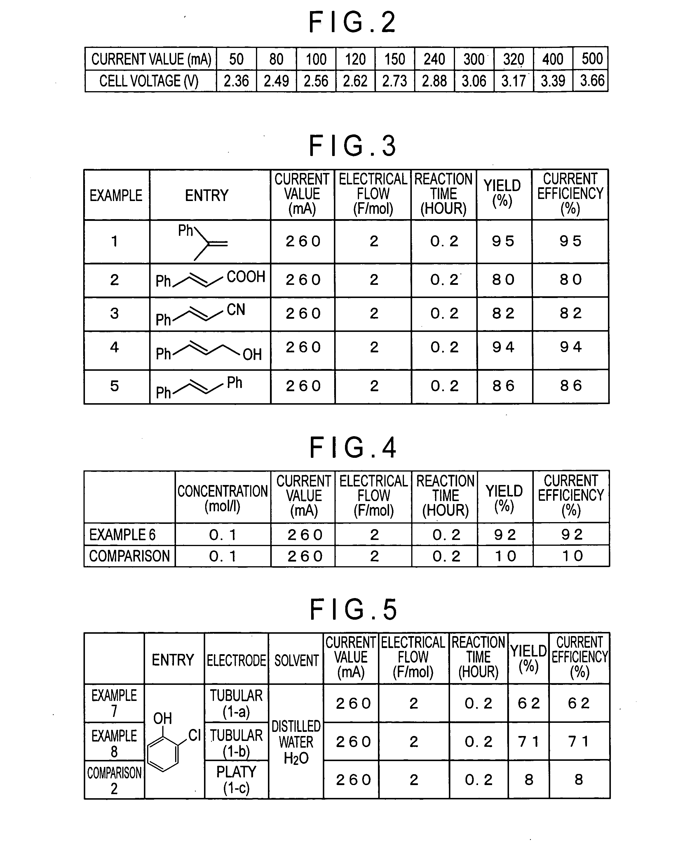
[0091] Hydrogenation reaction of an organic compound was conducted by using the hydrogenation apparatus 1 of the aforementioned embodiment.

(1) Modification of Inner Surface of Palladium Tube of Cathode 12 with Palladium Black:

[0092] Prior to hydrogenation reaction of the organic compound, palladium black was formed on an inner surface of a tubular member as the cathode 12 by electrolysis reduction treatment of palladium chloride according to the following procedure.

[0093] Around 100 to 300 mg of PdCl2 was added to a 1 M aqueous hydrochloric acid (HCl) solution and stirred to dissolve to a maximum extent. The prepared solution was circulated inside a palladium tube at a flow rate of 2.5 cm3 / min using a pressure feed pump or a pump for liquid chromatography.

[0094] Electrolytic reduction was conducted using the palladium tube (inner diameter 2.5 mm, length 8 cm) as a cathode at a constant current (80 mA / cm−2 to 500 mA / cm−2) (Translator's comment: correctly, 80 mA / cm2 to 500 mA / cm2...

example 6

[0098] Ethyl cinnamate was used as an unsaturated organic compound and hydrogenation was conducted under the same measurement conditions as those in Examples 1 to 5. Then, yield and current efficiency were obtained in the same way as described above. Measurement conditions and measurement results are shown in FIG. 4.


PUM

PropertyMeasurementUnit
Electric potential / voltageaaaaaaaaaa
Efficiencyaaaaaaaaaa

Abstract

An organic compound hydrogenation apparatus 1 of the present invention includes a reaction cell 13 to which an electrolytic solution is supplied, and an anode 11 and a cathode 12 arranged in the reaction cell 13, in which the cathode 12 is made of a material including a hydrogen storage material, the cathode being arranged as a tubular member so that an organic compound as an object to be treated circulates thereinside. The present invention having the arrangement described above can provide a method for hydrogenating organic compounds and an organic compound hydrogenation apparatus that can enhance efficiency of hydrogenation of the organic compound.

Description

TECHNICAL FIELD [0001] The present invention relates to an organic compound hydrogenation apparatus for conducting hydrogenation of an organic compound, and a method for hydrogenating the organic compound. BACKGROUND ART [0002] Conventionally, hydrogenation (hydrogenating) reaction of an organic compound and the like has been utilized in various chemical fields and, for example, such hydrogenation reactions are actually utilized as cracking reaction of petroleum in which heavy oil is hydrogenated to obtain gasoline or kerosene and tar fraction is hydrogenised so that it is liquefied to be matched for more purposive use conditions. Further, hydrogenation is utilized in a reaction in which an unsaturated hydrocarbon is converted into a corresponding saturated hydrocarbon, and a reaction in which a halogenated compound is dehalogenated. [0003] In addition, as a method for performing hydrogenation reaction safely and efficiently, there has been known a method in which an organic compoun...

Claims


Application Information

Patent Timeline
IPC IPC(8): C25B3/00C25B9/17C25B3/25
CPCC25B9/00C25B3/04C25B3/25C25B9/015C25B11/046C25B11/081
Inventor KOYAMA, SABUROTAKAGI, FUMIAKIFUCHIGAMI, TOSHIO
Owner IDEMITSU KOSAN CO LTD
Learn More