Welding joint for fuel tank

a welding joint and fuel tank technology, applied in the field of resin welding joints, can solve the problems of fuel permeation through a hose to the outside, insufficient fuel-impermeability of hdpe resin, and inability to meet the requirements of hose permeation, etc., to achieve high welding strength, improve water resistance, and improve the reliability of welding strength calculation

Inactive Publication Date: 2007-01-04
SUMITOMO RIKO CO LTD
View PDF4 Cites 14 Cited by
  • Summary
  • Abstract
  • Description
  • Claims
  • Application Information

AI Technical Summary

Benefits of technology

[0056] As described above, according to the first welding joint of the invention, the welding end surface of the outer layer member is projected toward the fuel tank from the welding end surface of the inner layer member. Also, the step-like portion is formed between the welding end surfaces. According to the first welding joint of the invention, when the weld portion of the first welding joint is welded to the fuel tank, first, the welding end surface of the outer layer member is welded to the fuel tank. Subsequently, the welding end surface of the inner layer member is welded to the fuel tank. Thus, there is no fear that a molten part of the inner layer member at the welding end surface may flow into a space between a part of the outer layer member, which is located at the side of the welding end surface, and the fuel tank and may disturb the welding therebetween. Consequently, according to the first welding joint of the invention, the weld portion can be welded to the fuel tank at high welding strength. Also, the reliability of calculation of the welding strength can be enhanced.
[0057] Also, the outer layer member made of HDPE resin excels in water resistance, as compared with the inner layer member including EVOH. Thus, even in a case where the weld portion is wetted down or where the weld down portion is immersed in water, the invention can obtain an advantage in that the welding strength can be maintained at a high level.
[0058] Next, according to the second welding joint of the invention, the welding end surface of the outer layer member and the welding end surface of the inner layer member are formed to be a slope or a curved surface so that the distance between the weld portion and the fuel tank gradually increases toward the inner end of the welding end surface of the inner layer member from the outer end of the welding end surface of the outer layer member. When the weld portion is welded, first, the welding end surface of the outer layer member is welded. Subsequently, the welding end surface of the inner layer member is welded. Also, a molten part of each of the outer layer member and the inner layer member flows from the outer end of the welding end surface to the inner end of the welding end surface. Thus, there is no fear that a part of the inner layer member, which is molten at the welding end surface, disturbs the welding between the outer layer member 38 and the fuel tank. Consequently, according to the second welding joint of the invention, the strength of the weld portion can be set at a high value. The reliability of the welding strength can be enhanced.
[0059] The third welding joint of the invention is configured so that an annular concave groove portion extending around the opening portion is provided at least one of a part of the welding end surface of the outer layer member, which is located at the side of the inner layer member, and a part of the welding end surface of the inner layer member, which is located at the side of the outer layer member. According to the third welding joint of the invention, even in a case where a part of the inner layer member is molten at the welding end surface when welded, the molten part of the inner layer member flows into the concave groove portion and is stopped therein. Thus, the molten part of the inner layer member is prevented from flowing into the welding end surface of the outer layer member. Consequently, according to the third welding joint of the invention, the strength of the weld portion can be set at a high value. Also, the reliability of the welding strength can be enhanced.
[0060] Meanwhile, the fourth welding joint of the invention is configured so that an annular projection extending around the opening portion and projecting toward the fuel tank is provided on a part of the welding end surface of the outer layer member, which is located at the side of the inner layer member. According to the fourth welding joint of the invention, when the weld portion is welded to the fuel tank, the partially projecting annular projection is first welded thereto. Thus, the molten part of the inner layer member is prevented from flowing into a part provided at the side of the outer layer member. Consequently, according to the fourth welding joint of the invention, the strength of the weld portion can be set at a high value. Also, the reliability of the welding strength can be enhanced.
[0061] Next, the fifth welding joint of the invention is configured so that an annular cutout portion extending around the opening portion and concaved from the inner surface of the inner layer member toward the outer layer member is provided in a part of the inner layer member, which is located higher than the welding end surface of the inner layer member. According to the fifth welding joint of the invention, the strength of the part of the inner layer member, which is located higher than the welding end surface, is reduced by the annular cutout portion. Thus, when the welding end surface of the inner layer member is pushed down toward the fuel tank after heat-molten, the inner layer member is deformed in a direction to fill in the cutout portion. Consequently, the molten part of the inner layer member can be prevented from flowing into a part provided at the side of the outer layer member. Thus, according to the fifth welding joint of the invention, the strength of the weld portion can be set at a high value. Also, the reliability of the welding strength can be enhanced.

Problems solved by technology

However, in recent years, from the viewpoint of environmental protection, regulations against the permeation of fuel through a hose to the outside have become strict.
Although the HDPE resin excels in weldability to the fuel tank, the HDPE resin is insufficient in fuel-impermeability.
This causes a problem in that the permeation of fuel to the outside occurs.
However, EVOH is not always sufficient in water resistance.
Thus, this configuration has a problem in that in a case where the weld portion is exposed to moisture for a longtime, the weld portion adsorbs moisture, with the result in deterioration of fuel impermeability and in lowering the degree of the welding strength thereof.
Therefore, in a case where the entire weld portion 250 is made of such a resin alloy material, the fuel impermeability and the welding strength may be deteriorated with time.

Method used


Image

  • Welding joint for fuel tank
  • Welding joint for fuel tank
  • Welding joint for fuel tank

Examples


Embodiment Construction

[0076] Next, embodiments of the invention is described in detail below with reference to the accompanying drawings.

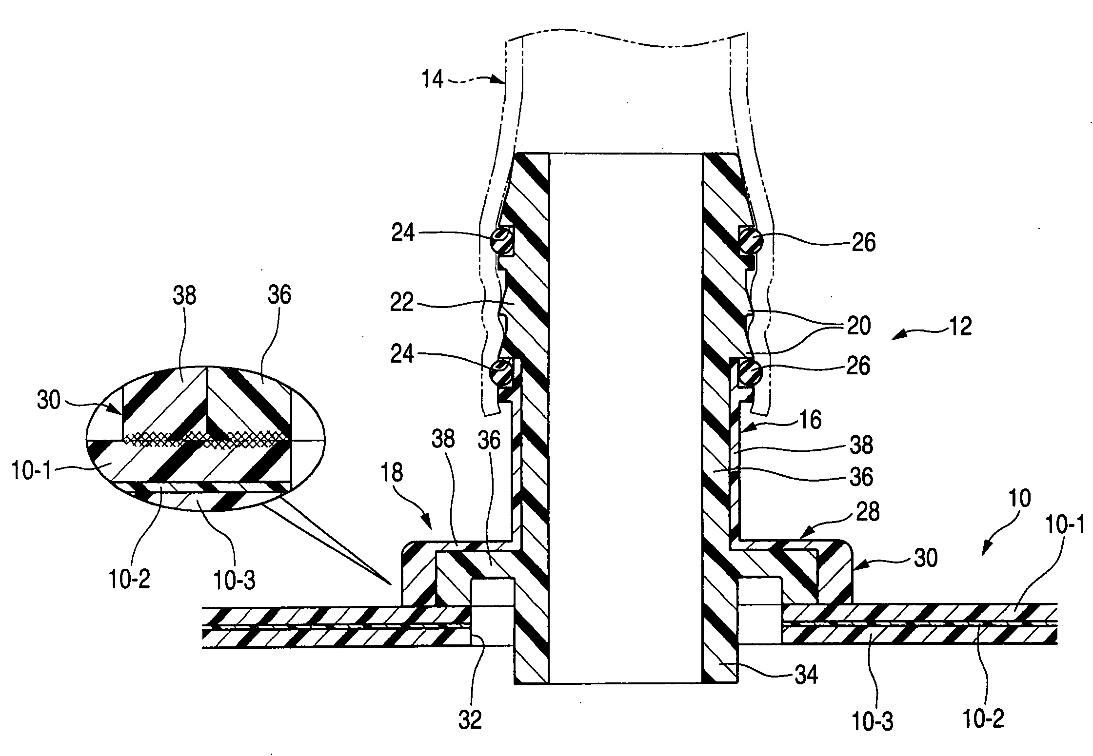
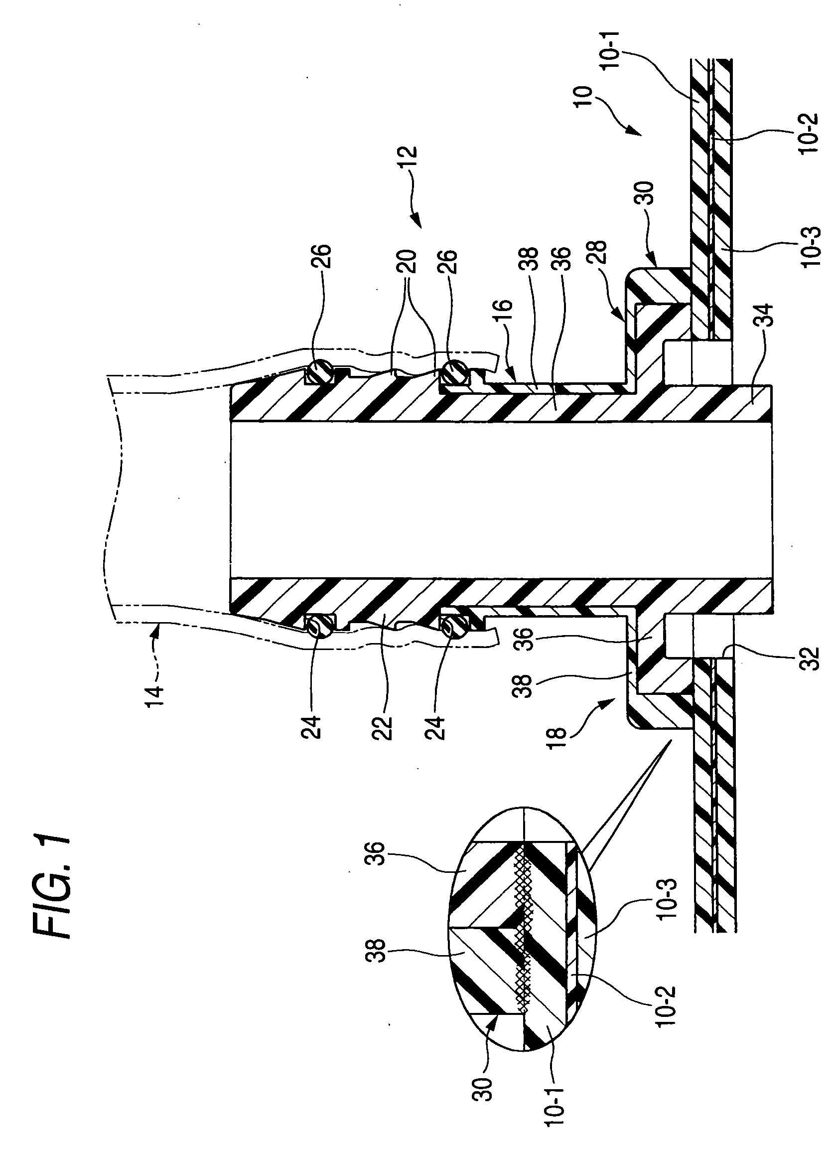
[0077] In FIG. 1, reference numeral 10 designates a resin fuel tank. In this embodiment, the resin fuel tank 10 has an outer layer member 10-1 and an inner layer member 10-3, which are made of HDEP resin. Also, the fuel tank 10 has a cross-sectional structure in which a thin barrier member 10-2 is sandwiched by the outer layer member 10-1 and the inner layer member 10-3.

[0078] Incidentally, the barrier member 10-2 also constitutes an inner layer opposed to the outer layer 10-1.

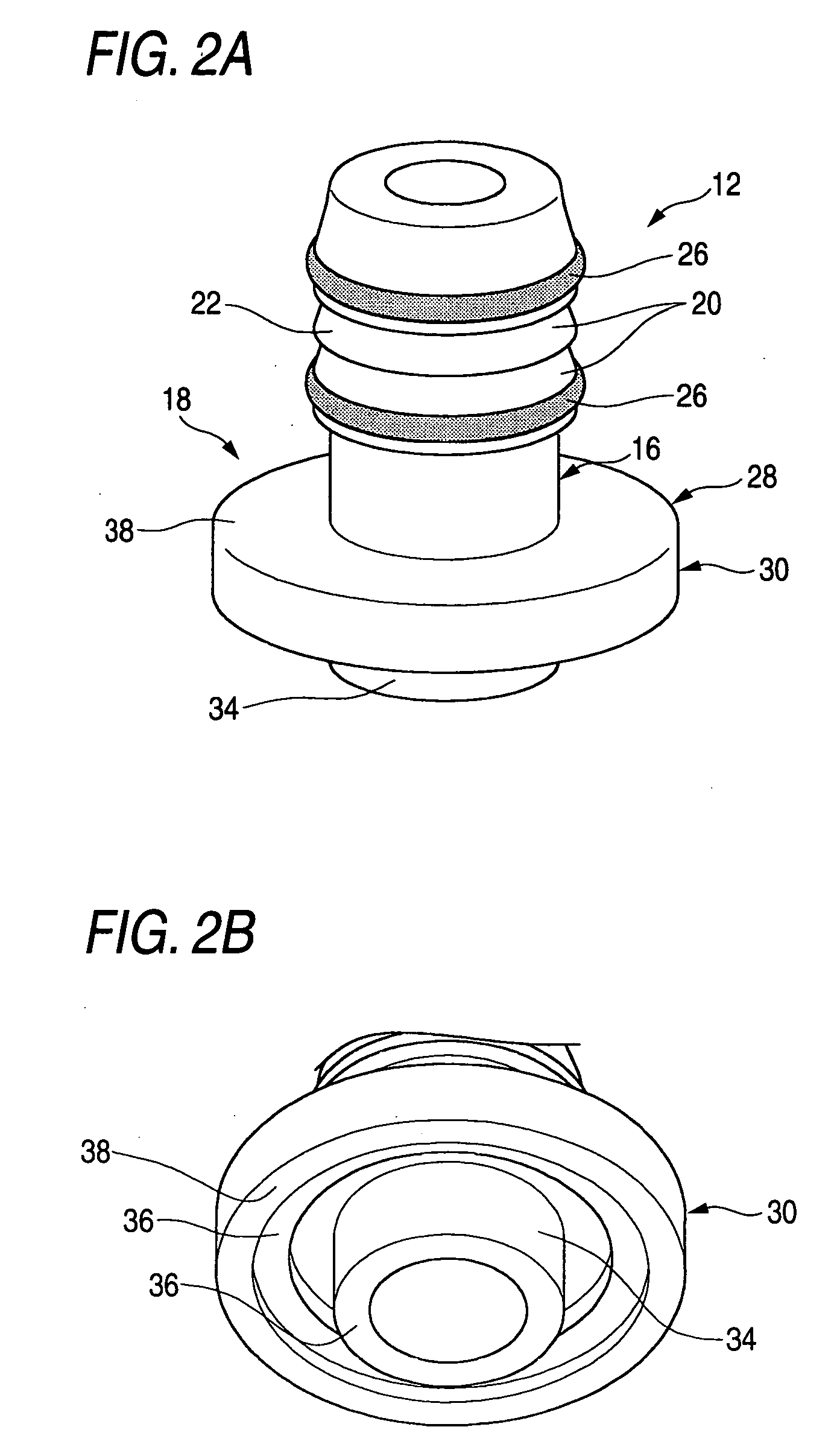
[0079] Reference numeral 12 denotes a resin welding joint that has a cylindrical portion 16, which serves as a connecting portion for a piping tube (hereunder referred to simply as a tube) 14, and a weld portion 18 that is a base end part thereof.

[0080] The tube 14 is press-fitted onto this cylindrical portion 16 and is connected to the fuel tank 10 through such a welding joint 12.

[0081] A cr...


PUM

PropertyMeasurementUnit
affinityaaaaaaaaaa
weldabilityaaaaaaaaaa
distanceaaaaaaaaaa

Abstract

A welding joint for a fuel tank includes a cylindrical portion and an annular weld portion. The weld portion has a multi-layer structure formed by layering an inner layer member made of a resin alloy material obtained by alloying a modified HDPE, to which a functional group having a high affinity to a hydroxyl group of EVOH is introduced, and EVOH, or by alloying the modified HDPE, normal HDPE and EVOH, and an outer layer member which uses the HDPE resin and/or modified HDPE resin and has high weldability to the fuel tank. Each of the inner and outer layer members is heat-welded to the fuel tank at a corresponding welding end surface. In a vicinity of at least one of the welding end surfaces of the inner outer layer members, a flow preventing portion that prevent a molten part of the inner layer member from flowing the outer layer member is provided.

Description

INCORPORATION BY REFERENCE [0001] The present application claims priority under 35 U.S.C. §119 to Japanese Patent Application No. 2005-192913 filed on Jun. 30, 2005. The content of the application is incorporated herein by reference in its entirety. BACKGROUND OF THE INVENTION [0002] 1. Field of the Invention[0003] This invention relates to a resin joint for connecting a piping tube or a connector to a resin fuel tank and, more particularly, to a resin welding joint that is welded to a fuel tank and that constitutes a connecting portion. [0004] 2. Description of the Related Art [0005] A fuel tank mounted in an automobile is provided integrally with a joint adapted to connect the fuel tank to a tube or a connector for leading fuel, which is injected from an oil filler port, to the fuel tank. [0006] Hitherto, for example, a rubber tube (or a rubber hose) has been used as the tube adapted to lead the fuel, which is injected from the oil filler port, to the fuel tank. However, in recent...

Claims


Application Information

Patent Timeline
Patent Type & Authority Applications(United States)
IPC IPC(8): B62D33/00
CPCB29C65/02B29C66/723B29C66/322B29C66/326B29C66/3282B29K2023/065B29K2023/086B29K2995/0067B29L2009/00B29L2031/7172B32B1/08B32B7/08B32B27/08B32B27/306B32B27/32B32B2307/7265B32B2605/00B60K15/03177B60K15/04B29C66/112B29C66/116B29C66/53247B29C66/131B29C66/8322B29C66/7234B29C66/71
Inventor NISHIYAMA, TAKAHIROKATAYAMA, KAZUTAKANIKI, NOBUAKI
Owner SUMITOMO RIKO CO LTD
Why Eureka
Try Eureka