Phase detecting circuit having adjustable gain curve and method thereof

a phase detection circuit and gain curve technology, applied in oscillation comparator circuits, automatic control of pulses, instruments, etc., can solve the problems of signal delay, difficult linear analysis of gain curves, and inability to smoothly trigger ultra-high frequency charge pumps

Active Publication Date: 2007-01-04
VIA TECH INC
View PDF7 Cites 66 Cited by
  • Summary
  • Abstract
  • Description
  • Claims
  • Application Information

AI Technical Summary

Problems solved by technology

However, when the phase detecting circuit 11 is the linear phase detector, the control signals UP, DN generated by the phase detecting circuit 11 operating at the ultra-high frequency cannot smoothly trigger the charge pump 12 to operate.
Because the phase detecting circuit 11 utilizes the bang-bang phase detector, which is a nonlinear element, it is very difficult to analyze the gain curve in a linear way.
However, these additional circuits also cause the signal delay between the phase detecting circuit 11 and the voltage control oscillator 14 and generate a larger jitter in the clock and data recovery circuit 1.
In addition, when the frequency of the data signal DATA is getting higher and higher, the phase detecting circuit 11 and the clock and data recovery circuit 1 also have to operate at the high-frequency to thus generate more noises, which deteriorate the circuit efficiency.
In addition, the cost of the high-frequency circuit is higher, and the costs of the phase detecting circuit 11 and the clock and data recovery circuit 1 also cannot be reduced.

Method used


Image

  • Phase detecting circuit having adjustable gain curve and method thereof
  • Phase detecting circuit having adjustable gain curve and method thereof
  • Phase detecting circuit having adjustable gain curve and method thereof

Examples


Embodiment Construction

[0033] The present invention will be apparent from the following detailed description, which proceeds with reference to the accompanying drawings, wherein the same references relate to the same elements.

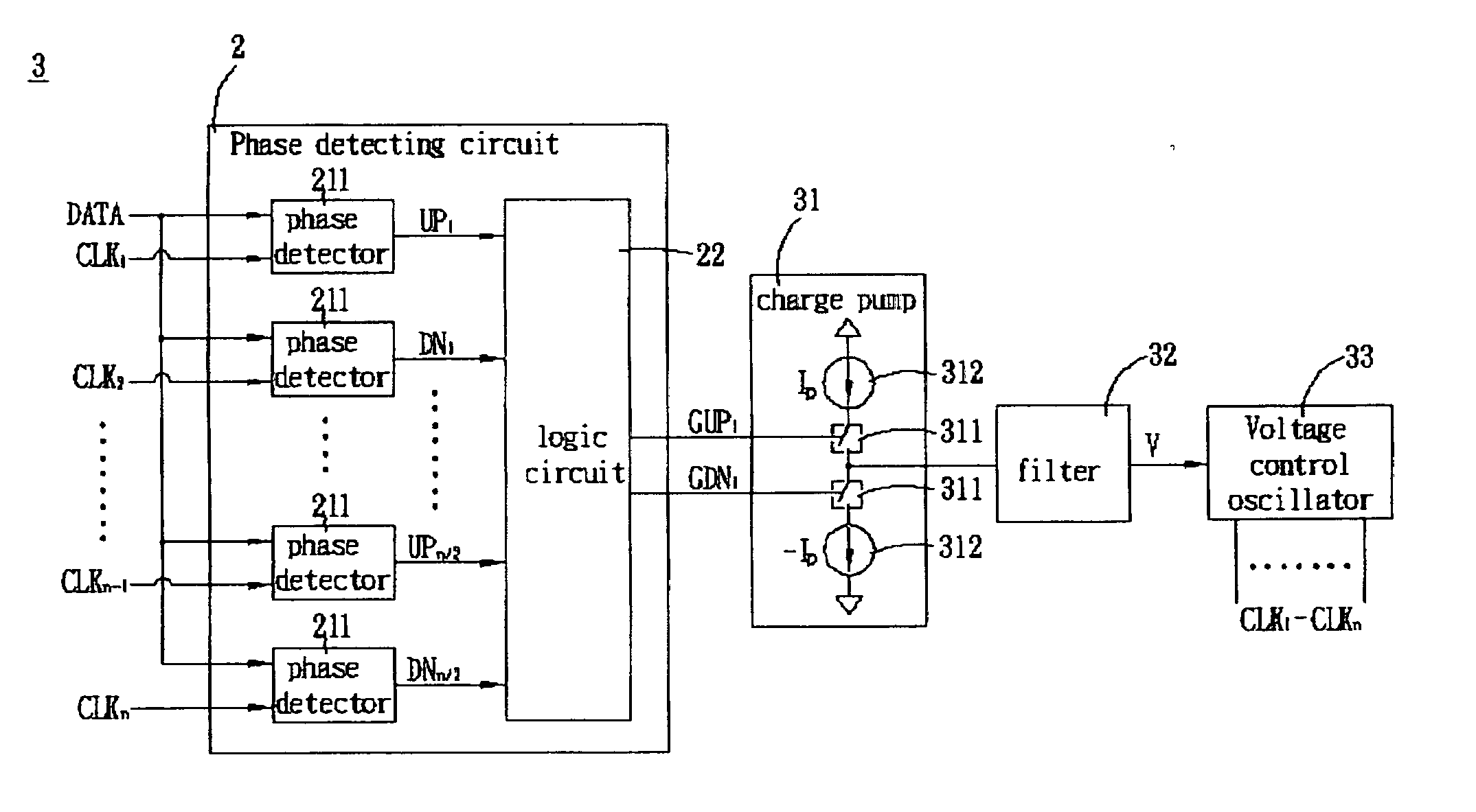
[0034]FIG. 6A is a block diagram showing a clock and data recovery circuit 3 according to an embodiment of the invention. Referring to FIG. 6A, the clock and data recovery circuit 3 includes a phase detecting circuit 2, a charge pump 31, a filter 32 and a voltage control oscillator 33. The phase detecting circuit 2 detects a phase difference between a data signal DATA and each of a plurality of clock signals CLK1-CLKn to generate two gain control signals GUP1, GDN1. The gain control signals GUP1, GDN1 control one set of switches 311 of the charge pump 31 to turn on one set of current sources 312. Thus, a current Ip outputted from or inputted to the set of current sources 312 charges / discharges the filter 32 to generate an output voltage V. The output voltage V controls the voltage c...


PUM


Abstract

A phase detecting circuit having an adjustable gain curve includes a plurality of phase detectors and a logic circuit The phase detectors detect phase differences between a data signal and a plurality of clock signals by comparison to output a plurality of control signals. The clock signals have the same frequency but different phases, and the frequency of the data signal is a multiple of the frequency of the clock signals. The logic circuit performs various logic operations according to these control signals to output at least one set of gain control signals for adjusting a gain curve of the phase detecting circuit.

Description

[0001] This application claims the benefit of U.S. Provisional Application Ser. No. 60 / 695,430, entitled “Binary Phase Detector”, filed Jul. 1, 2005.BACKGROUND OF THE INVENTION [0002] 1. Field of Invention [0003] The invention relates to a phase detecting circuit and a phase detecting method applied to a clock and data recovery circuit, and, in particular, to a phase detecting circuit, which has an adjustable gain curve and operates at a low frequency, and a method thereof. [0004] 2. Related Art [0005] In the modern communication system, the way of high-speed sequential signal transmission has gradually replaced the previous parallel signal transmission. During the high-speed sequential signal transmission, the original low-speed parallel signal has to be converted into a high-speed sequential signal first to facilitate the transmission. Thus, a clock generating circuit for generating a high-speed clock signal for sampling the high-speed sequential signal is needed. At the receiving...

Claims


Application Information

Patent Timeline
Patent Type & Authority Applications(United States)
IPC IPC(8): H03D13/00
CPCH03D13/004
Inventor LIN, JOANNA
Owner VIA TECH INC
Why Eureka
Try Eureka