Motor control system

a technology of motor control and control system, applied in the direction of electric controllers, ignition automatic control, instruments, etc., can solve the problems of torque ripple, increased current, and increased possibility of causing problems, and achieve the effect of low cost and high accuracy

Inactive Publication Date: 2007-01-04
HITACHI LTD
View PDF3 Cites 55 Cited by
  • Summary
  • Abstract
  • Description
  • Claims
  • Application Information

AI Technical Summary

Benefits of technology

[0018] According to the present invention, the motor cont...

Problems solved by technology

In other words, the control current of 100 A includes an error of about 10%, thus possibly causing the problem of a torque ripple, for example.
Particularly, when a small current flows, an influence of the offset error upon the control current is increased and the possibility of causing the problem becomes mo...

Method used


Image

  • Motor control system
  • Motor control system
  • Motor control system

Examples


first embodiment

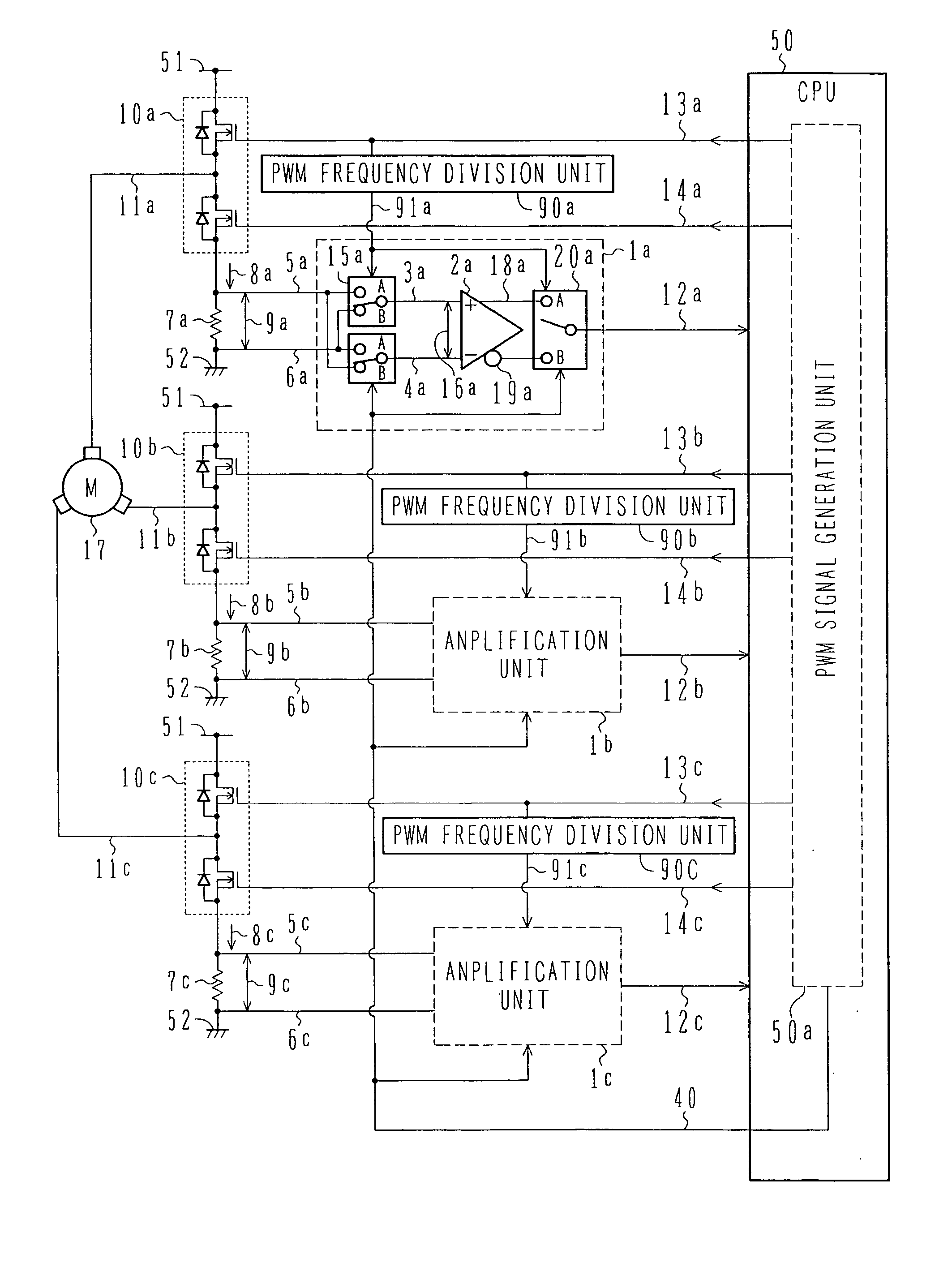
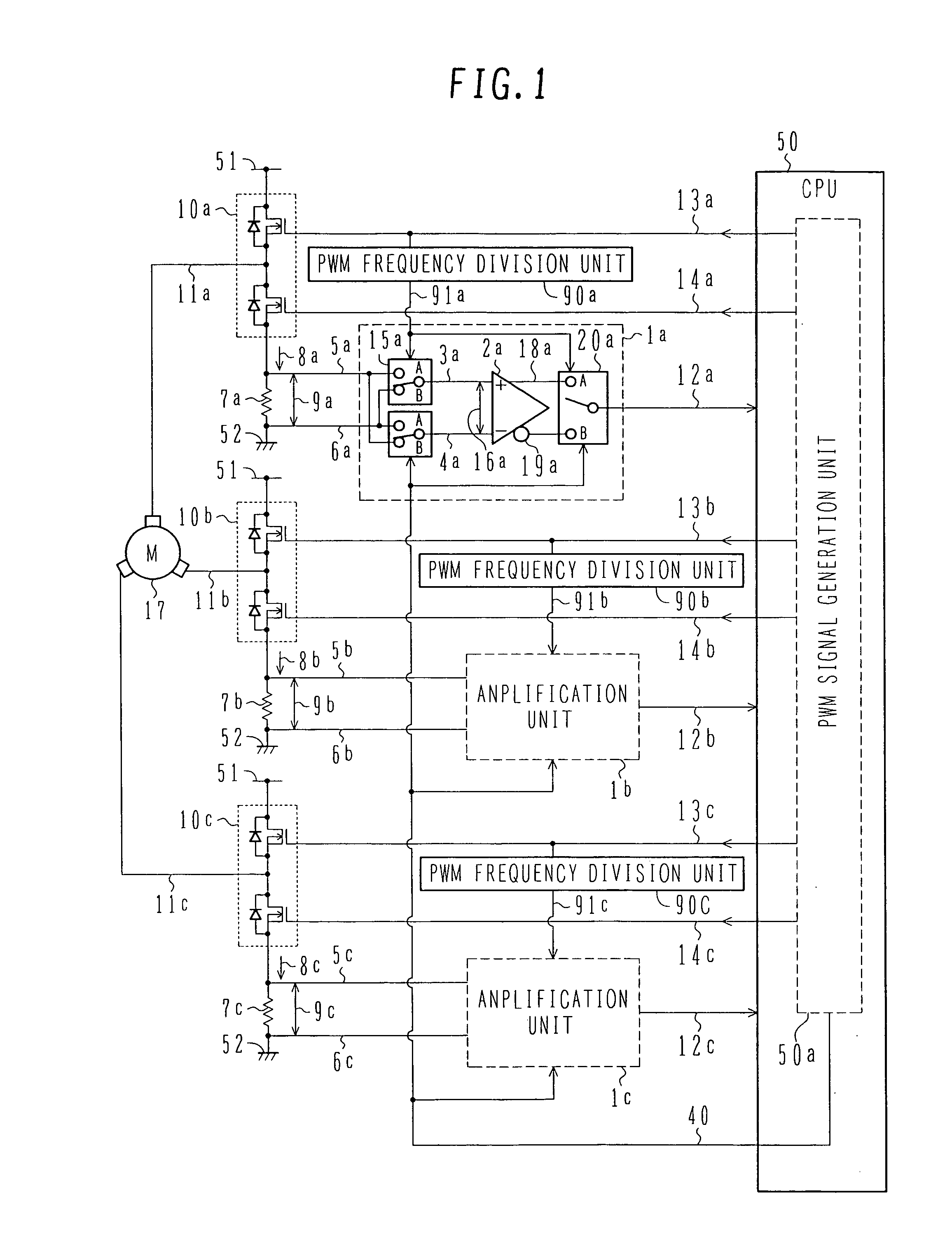
[0038]FIG. 1 is a circuit block diagram showing a motor driving-current sensing circuit according to a first embodiment of the present invention.

[0039] Referring to FIG. 1, reference numeral 1 (typically representing 1a, 1b and 1c for each of three phases) denotes an amplification unit for amplifying a voltage difference 9 across a current sensing resistor (shunt resistor) 7. The amplification unit 1 comprises an amplification circuit 2 for amplifying the difference between two positive (+) and negative (−) inputs, the amplification circuit 2 receiving a positive (+)-side input signal 3 and a negative (−)-side input signal 4 and outputting a positive gain output 18 and a negative gain output 19, an input switch unit 15 for alternately switching over connection between current sensing resistor terminal voltages 5, 6 and the positive (+)- and negative (−)-side input signals 3, 4 of the amplification circuit 2, and an output switch unit 20 for alternately switching over the two output...

second embodiment

[0061]FIG. 4 is a circuit block diagram showing a motor driving current sensing circuit according to a second embodiment of the present invention. In the following description of the second embodiment, a description of the same components as those in the first embodiment is omitted.

[0062] In FIG. 4, reference numeral 21 denotes a voltage smoothing unit for smoothing the amplification unit output voltage 12 outputted from the amplification unit 1, and 68 denotes an average voltage. Further, a current sensing resistor (shunt resistance) 7 is disposed between the high-side switch and the low-side switch of the driving switch circuit 10, and voltages at opposite terminals of the current sensing resistor 7 are inputted to the amplification unit 1.

[0063] The operation of this second embodiment will be described below with reference to FIG. 5.

[0064] As shown in FIG. 5, when the driving current for driving the motor 17 is supplied by turning on / off the driving switch circuit 10 in accord...

third embodiment

[0066]FIG. 7 is a circuit block diagram showing a motor driving current sensing circuit according to a third embodiment of the present invention. A description of the same components as those in the foregoing embodiments is omitted here. In FIG. 7, reference numeral 24 denotes a voltage shift unit disposed between the amplification unit 1 and the CPU 50 to receive the amplification unit output voltage 12.

[0067]FIG. 8 is a timing chart showing the operation of the motor driving current sensing circuit according to the third embodiment.

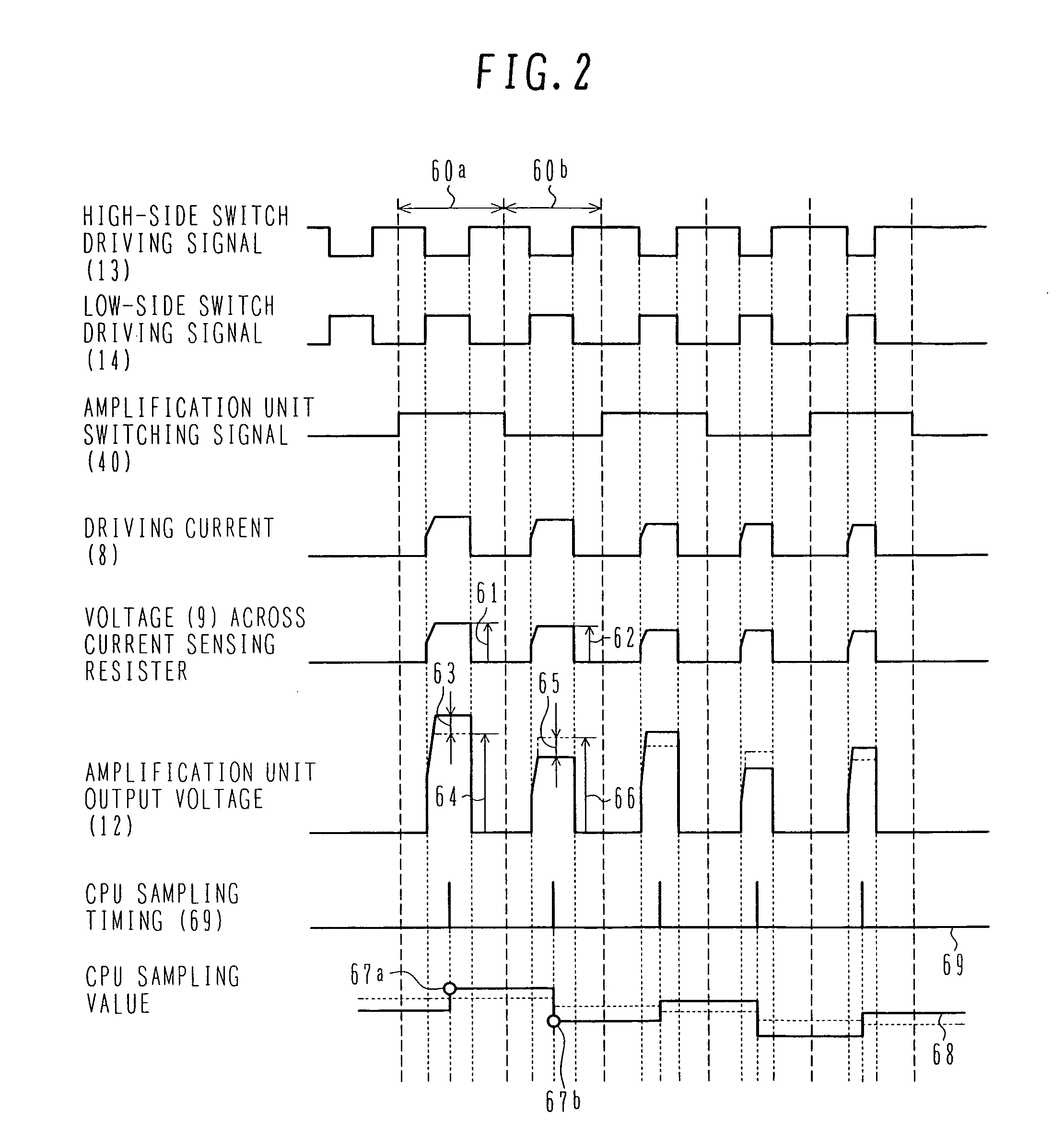
[0068] When the motor driving current is supplied by turning on / off the driving switch circuit 10 in accordance with the high-side switch driving signal 13 and the low-side switch driving signal 14, the driving current 8 flows through the current sensing resistor 7 and a waveform indicated by a voltage 9 across the current sensing resistor is detected between the opposite terminals of the current sensing resistor 7. When the voltage 9 is very small an...


PUM


Abstract

A motor control system which can realize current detection with high accuracy by using an amplifier having an ordinary level of accuracy and can avoid deterioration of current detection accuracy even when emperature is changed. The motor control system comprises a switch circuit for supplying a driving current to a motor, a resistor for detecting the driving current, an amplification circuit for amplifying a potential difference across the resistor, an input section switch unit disposed in an input section of the amplification circuit and changing over the potential difference to be forward biased or reverse biased, an output section switch unit disposed in an output section of the amplification circuit and changing over an output voltage of the amplification circuit to be forward biased or reverse biased, and a CPU for averaging a voltage produced when the output voltage of the amplification circuit is forward biased, and a voltage produced when the output voltage of the amplification circuit is reverse biased.

Description

BACKGROUND OF THE INVENTION [0001] 1. Field of the Invention [0002] The present invention relates to a motor control system, and more particularly to a motor control system for a three-phase brushless DC motor which is used, for example, as an assisting motor in an electric power steering system. [0003] 2. Description of the Related Art [0004] Recently, a technique for assisting torque by using a motor instead of a conventional hydraulic power assisting system has been brought into practice for the purpose of reducing the vehicle weight and improving fuel economy. [0005] For example, a three-phase brushless DC motor, which is a comparatively quick-responsive, can produce high torque, and is easy to control, is used as an assisting motor in an electric power steering (EPS) system. In the three-phase brushless DC motor, the produced torque is changed in proportion to a current. To accurately control the three-phase brushless DC motor, therefore, the current flowing through the motor r...

Claims


Application Information

Patent Timeline
IPC IPC(8): H02H7/08B62D5/04H02P27/06H02P27/08
CPCH02M2001/0009H02M7/53873H02M1/0009
Inventor WATANABE, MITSUHIKOOYAMA, KATSUYASASAKI, SHOJI
Owner HITACHI LTD
Why Eureka
Try Eureka