Data recovery using data eye tracking

a data eye and eye tracking technology, applied in the field of data communication, can solve the problems of high nonlinearity, inability to correctly track the eye center, and dependence of analog signals on data patterns

Inactive Publication Date: 2007-01-04
SUPER INTERCONNECT TECH
View PDF11 Cites 31 Cited by
  • Summary
  • Abstract
  • Description
  • Claims
  • Application Information

AI Technical Summary

Benefits of technology

[0010] A described embodiment of the present invention provides a data recov...

Problems solved by technology

However, at very high operating frequencies, analog signals depend on the data pattern and become highly nonlinear because they do not settle during the bit duration.
But if the received data stream has a jitter comparable to a bit time or is heavily distorted by the channe...

Method used


Image

  • Data recovery using data eye tracking
  • Data recovery using data eye tracking
  • Data recovery using data eye tracking

Examples


first embodiment

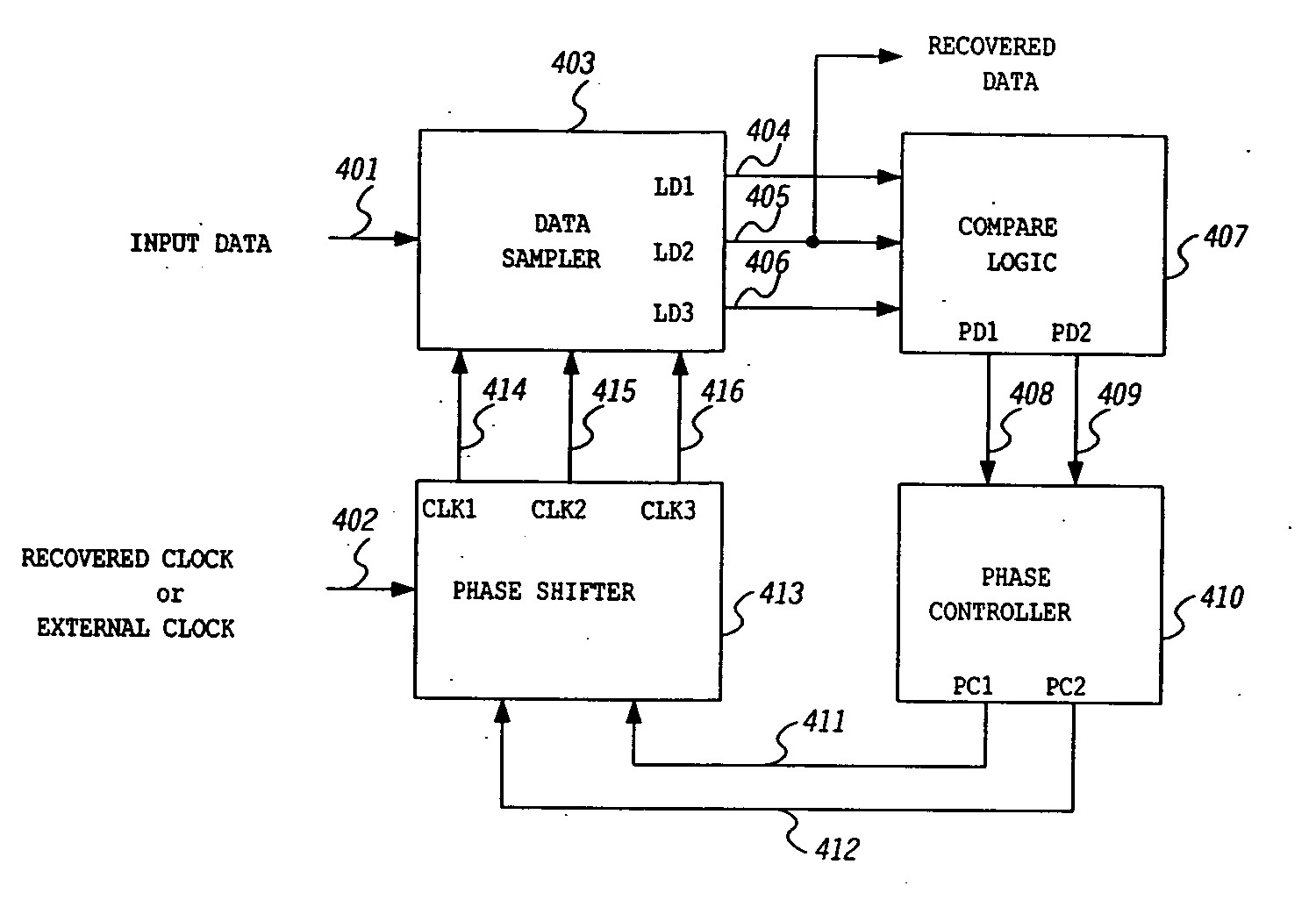
[0035]FIG. 7 shows phase shifter 413, including a phase delay(I) 707, a phase advance 708, and a phase delay (II) 709. Phase delay(I) 707 is used to adjust the phase of ‘CLK2’415 under control of ‘PC1’411. Phase delay 707 can be made up of a cascade of MOSFET inverters or a resistor-capacitor (RC) delay circuit, where ‘PC1’411 acts as the bias current or bias voltage. Phase advance 708 and phase delay (II) 709 are used to adjust the phase difference of ‘CLK1’414 and ‘CLK3’416 from ‘CLK2’415.

second embodiment

[0036]FIG. 8 shows the phase shifter 413, which comprises four variable delays 801, 804, 805, 808 and further comprises a phase detector and a loop filter 806. Variable delay(I) 801 is controlled by ‘PC1’411 and adjusts the phase of its output 802. Variable delay(II) 804, variable delay(III) 805, and phase detector and loop filter 806 make up delay-locked loop 803, which makes the phase of ‘CLK2’415 tracks the phase of variable delay(I)'s output 802. Variable delay(III) 805 is controlled by ‘PC2’412 and adjusts the phase difference between ‘CLK1’414 and ‘CLK2’415. Variable delay(IV) 808 is a replica of variable delay(III) 805 and is also controlled by PC2’412. Therefore, the phase difference between ‘CLK2’415 and ‘CLK3’416 is the same as that between ‘CLK1’414 and ‘CLK2’415.

third embodiment

[0037]FIG. 9 shows phase shifter 413. It comprises variable delay 901, phase distributor 903, multiplexer(I) 907, multiplexer(II) 909, buffer 908, and selection logic 910. Variable delay 901 has the same function as variable delay(I) 801 in FIG. 8. Phase distributor 903 is a kind of delay-locked loop or phase-locked loop that makes multiples of different phase clocks 904, 905, 906, where the phase of 905 tracks the phase of 902. Here 904 is a bundle of clocks that lead 905 in phase, where the amount of phase leading lies between zero and half bit time. Selection logic 910 controls multiplexer(I) 907 so that it passes one of multiple input clocks 904. Therefore, the phase difference of ‘CLK1’414 and ‘CLK2’415 can be adjusted by ‘PC2’412. Bundle of clocks 906 that lag 905 in phase are input to multiplexer(II) 909, where one of those is selected so that the phase difference between ‘CLK2’415 and ‘CLK3’416 is the same as that between ‘CLK1’414 and ‘CLK2’415. The purpose of buffer 908 is...


PUM


Abstract

A data recovery system for a serial digital data link includes a data sampler, compare logic, a phase controller, and a phase shifter. The data sampler samples input data three times in a bit time which time is determined by clock pulses generated by the phase shifter, and recovers digital data according to a predetermined decision criterion. Data sampling phases are split so as to track the data eye. The compare logic compares the output of the data sampler according to a predetermined method. Phase controller uses the output of the compare logic and generates phase control signals. These signals are set so as to control the sampling times of the data sampler and to attain near optimally recovered data stream. The phase shifter uses the phase control signals and makes three different phase clocks from input clock. The input clock can be an external clock, or can be recovered from the external clock or input data stream.

Description

CROSS REFERENCE TO RELATED APPLICATIONS [0001] This application is a continuation of U.S. application Ser. No. 09 / 943,029, filed Aug. 29, 2001, which application claims priority under 35 U.S.C. §119(e) to U.S. application Ser. No. 60 / 229,369, filed Aug. 30, 2000, which applications are incorporated by reference herein in their entirety.BACKGROUND OF THE INVENTION [0002] 1. Technical Field [0003] This invention relates generally to data communications, and more specifically to data recovery for serial digital data link. [0004] 2. Description of the Related Art [0005] A number of digital data recovery systems are based on a sampling recovery method that uses sampled data to control the data sampling time. For example, Rau discloses a method for serial non-return-to-zero (NRZ) data transmission. See Rau et al., “Clock / Data Recovery PLL Using Half-Frequency Clock,” IEEE Journal of Solid-State Circuits, pp. 1156-1160, No. 7, July 1997. Rau includes a general feature of phase-locked loops...

Claims


Application Information

Patent Timeline
IPC IPC(8): H04L7/00H03L7/08H03L7/081H03L7/091H04L7/02H04L7/033H04L25/02
CPCH03L7/081H03L7/0812H04L7/0037H03L7/091H04L7/0337H03L7/0814
Inventor LEE, SANG-HYUNJEONG, DEOG-KYOON
Owner SUPER INTERCONNECT TECH
Why Eureka
Try Eureka