Porous ceramic heating element and method of manufacturing thereof

a heating element and porous ceramic technology, applied in the direction of heater elements, resistive material coatings, natural mineral layered products, etc., can solve the problems of element generation of poisonous gas, reduced heat storage ability, and general weak mechanical strength of the structure of the porous ceramic heating element, so as to accelerate the formation of foam and prevent the discharge

Inactive Publication Date: 2007-01-04
KIM CHANGHEE +1
View PDF1 Cites 12 Cited by
  • Summary
  • Abstract
  • Description
  • Claims
  • Application Information

AI Technical Summary

Benefits of technology

[0025] As described above, the porous ceramic heating element and the method of manufacturing thereof according to the present invention has the following effects.
[0026] First, steel slag and blast-furnace slag discharged from an iron works are used as an inorganic material, thereby obtaining advantages of recycling resources and environmental affinity.
[0027] Second, bonding strength of porous foam formed in a ceramic heating element becomes strong, thereby providing a porous ceramic heating element in which the entire structure is hardened.
[0028] Third, methyl hydrogen polysiloxane is used as a foaming agent, thereby accelerating the formation of foam and preventing the discharge of harmful gas during firing process in a low temperature.

Problems solved by technology

However, the related art porous ceramic heating element have disadvantages that the bonding strength of pores formed inside is so weak that the mechanical strength of the structure of the porous ceramic heating element generally becomes weak, and the ability of storing heat is decreased.
However, if the porous ceramic heating element is heated in a high temperature, such porous ceramic heating element generates a poisonous gas carbonizing an added organic foaming agent.
In addition, the porous ceramic heating element has disadvantages of shape restriction and economic difficulty due to a high sintering temperature of over 1100° C. and a process complexity.

Method used


Image

  • Porous ceramic heating element and method of manufacturing thereof
  • Porous ceramic heating element and method of manufacturing thereof
  • Porous ceramic heating element and method of manufacturing thereof

Examples


Embodiment Construction

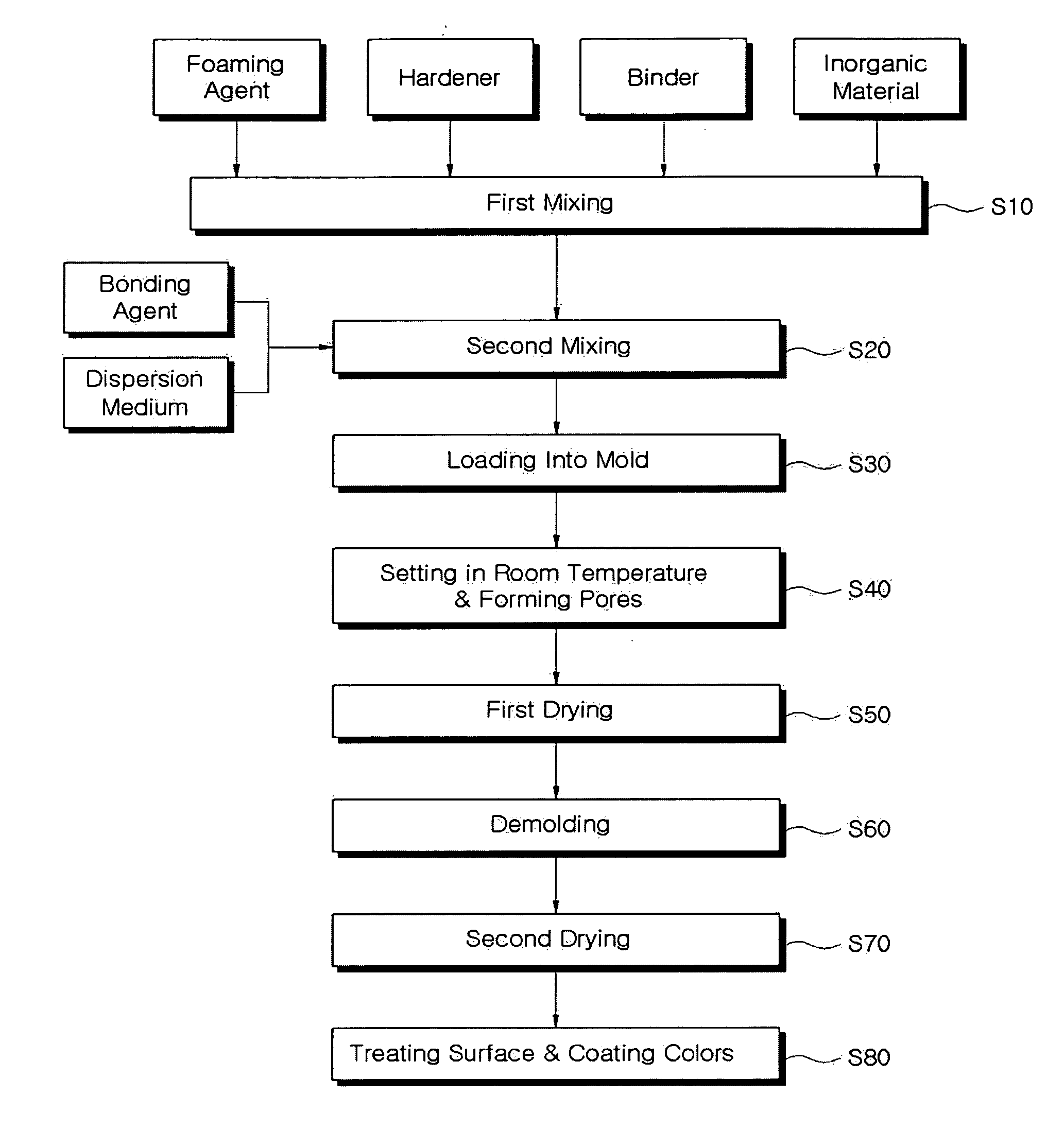
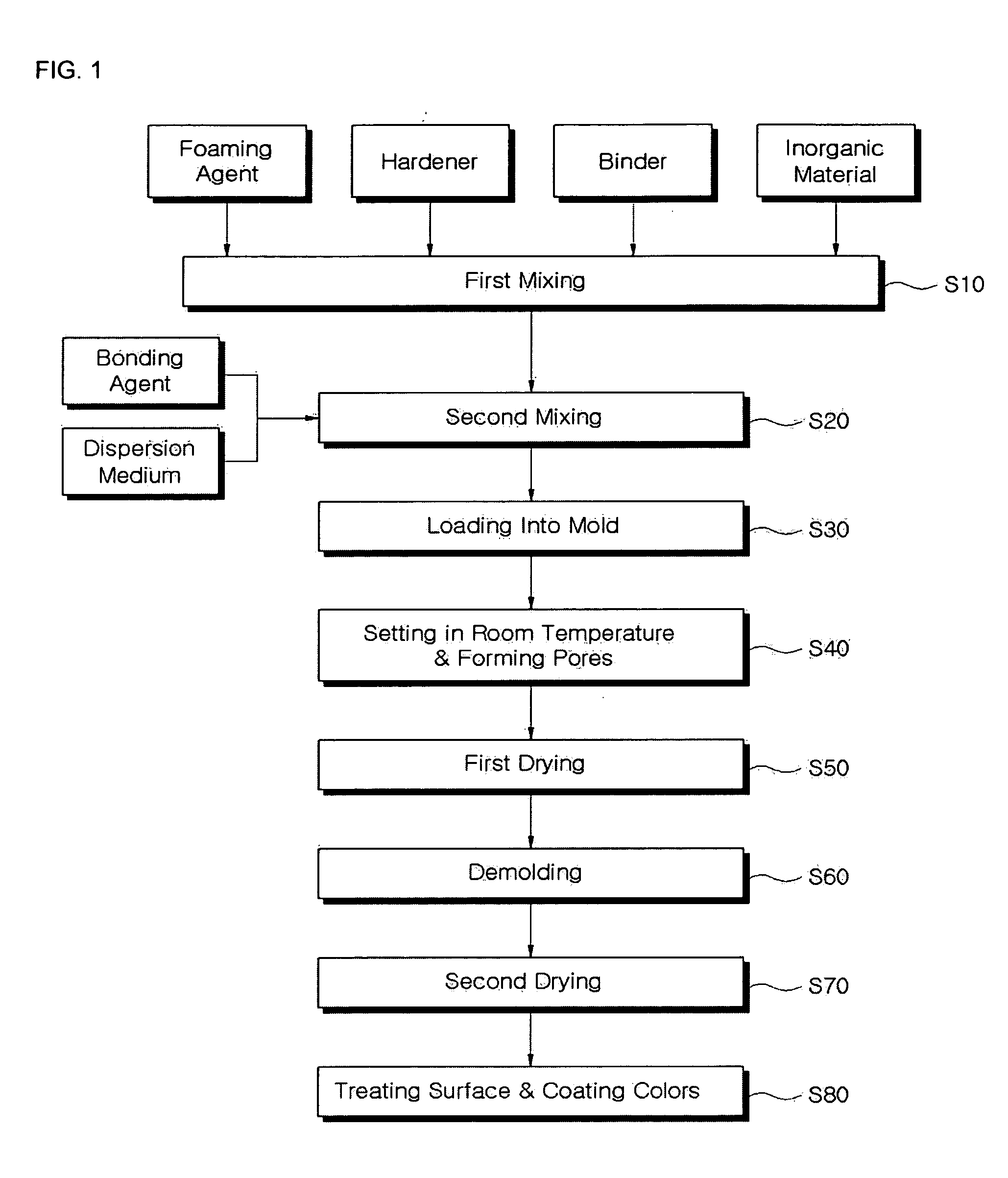
[0032] The present invention provides a porous ceramic heating element wherein 0.08 to 1.00 wt % of a foaming agent is added in 99.00 to 99.92 wt % of a mixture of an inorganic material, a binder, a conductive material, a hardener, a bonding agent and a dispersion medium and mixed with the mixture.

[0033] Herein, the bonding agent and the hardener have a tetrahedron structure by a condensation polymerization reaction, and the tetrahedron structure forms silica gel by cross-linking with metal or fixing of metal.

[0034] Assuming that the mixture is 100wt %, the inorganic material is a nonflammable material forming 40 to 66 wt % of the mixture and a packing material for the frame of a final molded product. Herein, the inorganic material may be selected one composition or mixture by mixing at least two selected compositions among industrial by-products such as steel slag and blast-furnace slag, metal oxide systems such as alumina (Al2O3) and mullite (3Al2O3·2SiO2), metal carbide systems...


PUM

PropertyMeasurementUnit
wt %aaaaaaaaaa
wt %aaaaaaaaaa
wt %aaaaaaaaaa

Abstract

The present invention provides a porous ceramic heating element wherein 0.08 to 1.00 wt % of a foaming agent is added in 99.00 to 99.92 wt % of a mixture of an inorganic material, a binder, a conductive material, a hardener, a bonding agent and a dispersion medium and mixed with the mixture. According to the porous ceramic heating element, the bonding strength of porous foam formed in the ceramic heating element becomes strong, thereby providing an effect that the entire structure is hardened.

Description

TECHNICAL FIELD [0001] The present invention relates to a porous ceramic heating element and a method of manufacturing thereof, and more particularly, to a porous ceramic heating element recycling steel slag and blast-furnace slag discharged from an iron works as an inorganic material and adding methyl hydrogen polysiloxane as a foaming agent for providing porosity and a method of manufacturing the porous ceramic heating element using said materials in a low temperature. BACKGROUND ART [0002] In general, a porous ceramic artificially form a large number of pores inside a ceramic and are used as lightweight construction materials within the specified extent because of its low specific gravity and lightness in weight. Moreover, the porous ceramic is variously used as various kinds of filters, instrumental materials for firing, deodorizers, heat insulating materials, soundproofing materials and heating materials. [0003] In this porous ceramic heating element and method of manufacturing...

Claims


Application Information

Patent Timeline
Patent Type & Authority Applications(United States)
IPC IPC(8): B32B9/00B29C65/00C04B24/42C04B33/04C04B33/132C04B35/117C04B35/185C04B35/19C04B35/195C04B35/20C04B35/56C04B35/565C04B35/581C04B35/584C04B35/63C04B38/00C04B38/02
CPCC04B24/42Y10T428/24917C04B33/1328C04B33/138C04B35/117C04B35/185C04B35/19C04B35/195C04B35/20C04B35/56C04B35/5611C04B35/565C04B35/581C04B35/584C04B35/6263C04B35/6316C04B38/02C04B2103/42C04B2111/28C04B2111/52C04B2235/3201C04B2235/3203C04B2235/3206C04B2235/3217C04B2235/3248C04B2235/3262C04B2235/3284C04B2235/3409C04B2235/3427C04B2235/3445C04B2235/3463C04B2235/3481C04B2235/425C04B2235/5445C04B2235/77C04B2235/80C04B2235/96C04B33/04Y10T29/49099Y10T29/49082C04B35/18C04B38/0054C04B35/00Y10T428/249967Y02P40/60H05B3/14C04B38/10
Inventor KIM, CHANGHEEKIM, TAEHEE
Owner KIM CHANGHEE
Why Eureka
Try Eureka