Centrifuge assembly

a centrifuge and assembly technology, applied in centrifuges and other directions, can solve the problems of unpreventable lateral jiggling, damage or distortion of the drive spindle and motor, vibration and flexure of the spindle, etc., to minimize the detrimental thermal effect, improve the airflow characteristics, and minimize the effect of specimen warming

Inactive Publication Date: 2007-01-04
CENTURION LLC
View PDF0 Cites 84 Cited by
  • Summary
  • Abstract
  • Description
  • Claims
  • Application Information

AI Technical Summary

Benefits of technology

[0025] It is another principal object of the present invention to provide a centrifuge system wherein a pivoting motion of a biomedical material sample holder is consistently smooth and uniform, to effect the desired separation.
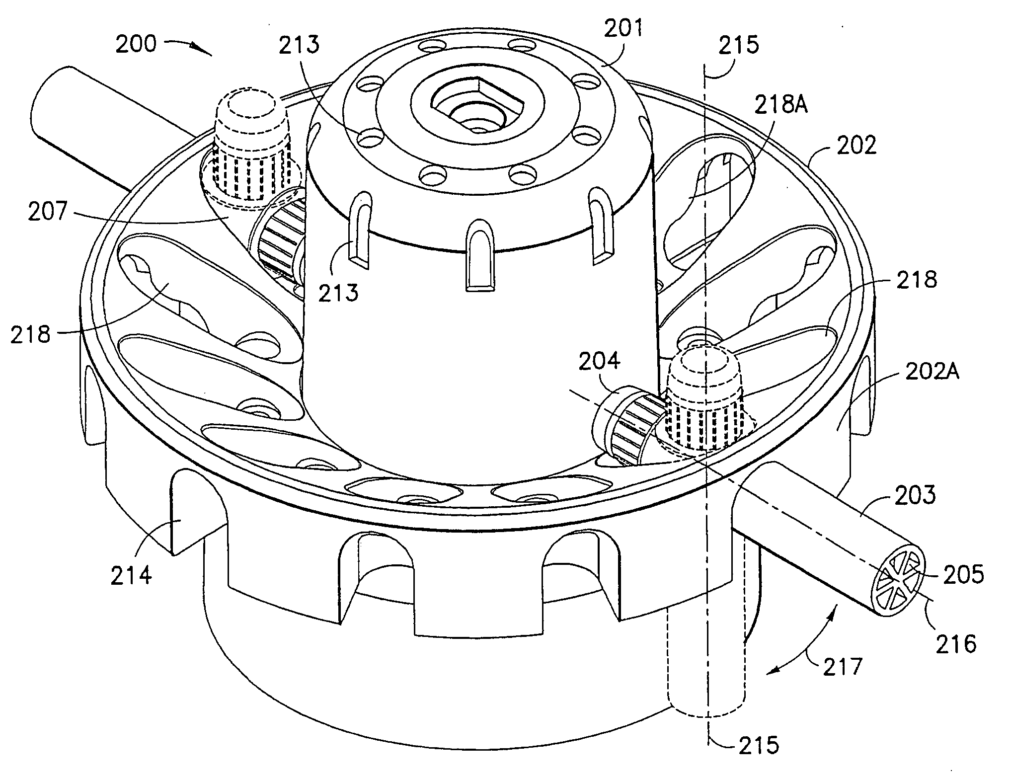
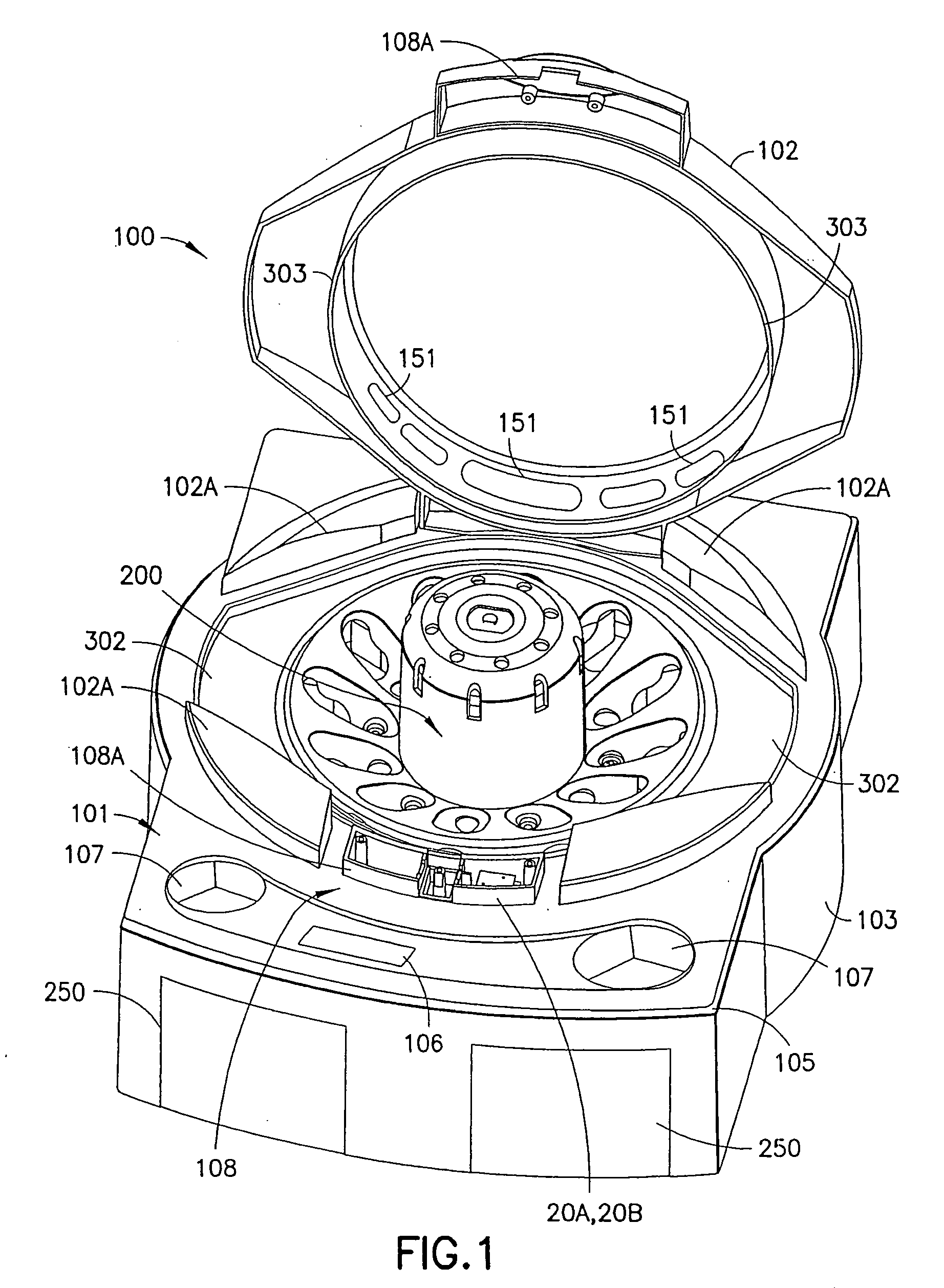
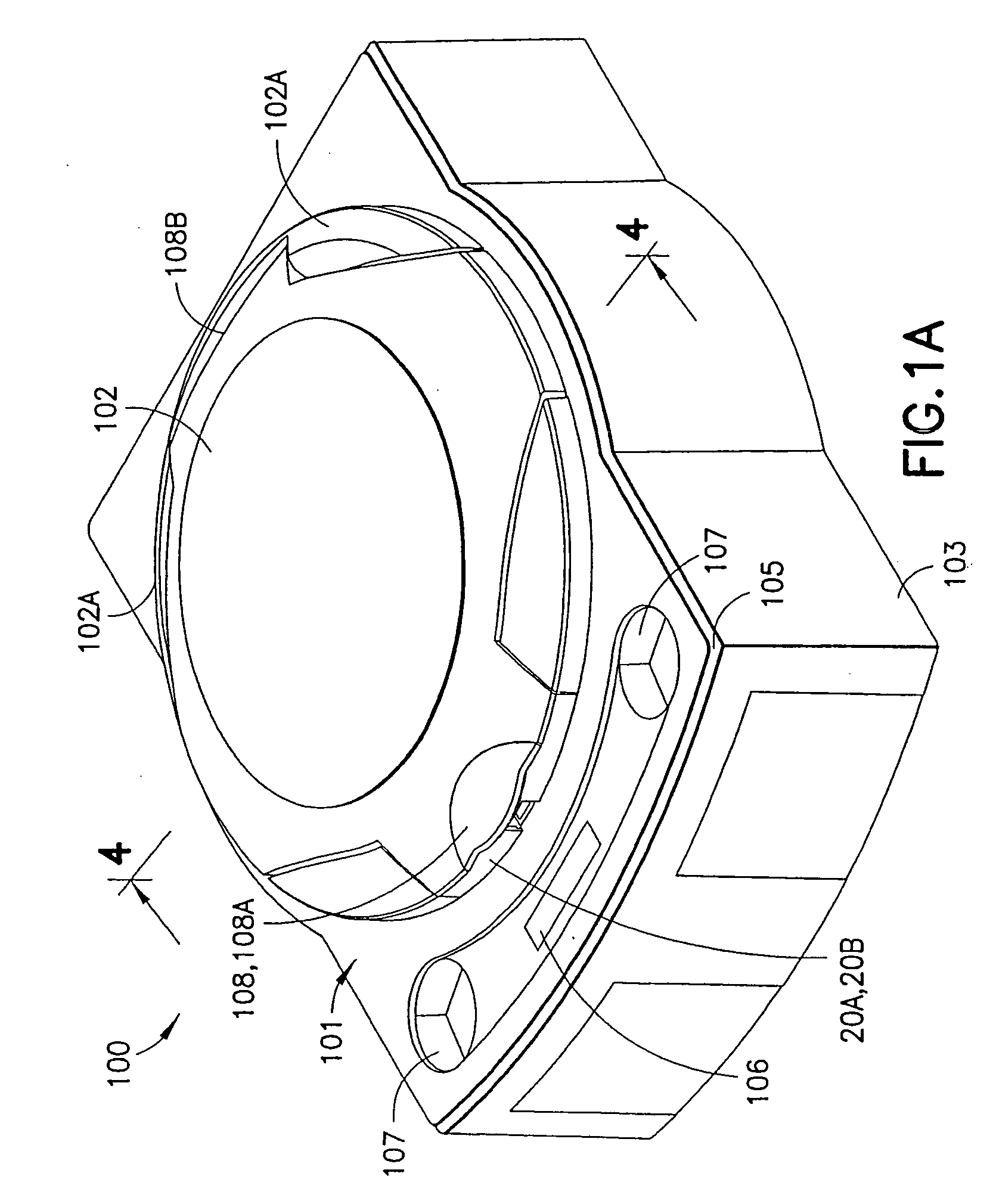
[0036] The present improved centrifuge system includes a drive motor mounted independently relative to a sample carrier that minimizes detrimental forces born by a motor drive shaft. The sample tube carrier includes a rotating center operably connected to the drive motor. The drive motor cooperates with a resilient mounting system aiding self-centering, and force and vibration compensation, while improving motor life. In a selected embodiment, the sample carrier and a tube member provide respective operably cooperable contoured surfaces enabling relative smooth pivoting motion during use, minimizing sample vibration, and improving a desired sample separation while minimizing sample remixing. In another embodiment, a thermal management and airflow system minimize thermal damage and undesired thermal gradients during operation.

Problems solved by technology

At high rpm, the spindle would be subject to vibration and flexure, with concomitant adverse resultant forces applied to the flowable sample material.
Such vibration and flexure causes damage or distortion in and to the drive spindle and motor.
Conventional pivoting mechanism often gripped only the top portion of a sample tube, and as such do not prevent unwanted lateral jiggling.
The pivot mechanism or structure often imparted ragged and jerky movements to the tube resulting in undesirable remixing and less than desired control of the material flow undergoing centrifugal forces.
Intermixing of the separable phases reduces the effectiveness of the fibrin web system.
Beretta et al. does not provide for minimizing intermixing, or for readily increasing a size of the fibrin membrane to a beneficial size or adaptive geometry, and fails in provide a system for manufacturing custom shaped fibrin membranes.
The Grippi et al. method applies thinning and stretching forces to the film that prove a detriment to process control.
Grippi et al. fails to aid the production of fibrin products by either increasing volume, or decreasing processing time and limiting damaging operable vibrations, and also fails to increase production in convenient shapes and sizes for use, without employing complicated post centrifuge separation and unrolling processing steps.
Sample preparation has often been a bottleneck to the analysis of complex biological materials, especially in high throughput automated applications employing multiple sample sets such as genotyping and DNA sequencing.

Method used


Image

  • Centrifuge assembly
  • Centrifuge assembly
  • Centrifuge assembly

Examples


Embodiment Construction

[0081] Reference will now be made in detail to several embodiments of the invention that are illustrated in the accompanying drawings. Wherever possible, the same or similar reference numerals are used in the drawings and the description to refer to the same or like parts or steps. The drawings are to be understood as being in simplified form and are not to a precise scale or perspective.

[0082] For purposes of convenience and clarity only, directional terms, such as top, bottom, up, down, over, above, and below may be used with respect to the drawings. Similarly, directional markings including arrows or dashed alternative position lines may depict motion or action. These and similar directional terms and indicators should not be construed to limit the scope of the invention in any manner. The words “connect,”“couple,”“support,” and similar terms with their inflectional morphemes do not necessarily denote direct and immediate connections, but also include connections through mediate...


PUM


Abstract

A centrifuge system includes a drive motor mounted independently relative to a sample carrier to eliminate detrimental forces born by a motor drive shaft. The rotatable sample carrier or tray includes a rotating center operably connected to the drive motor. The drive motor cooperates with a resilient mounting system enabling self-centering, force and vibration compensation, and improving motor life. The rotatable sample tray and a sample tube holder have respective operably cooperative contoured surfaces enabling relative smooth pivoting motion in the sample tube holder during rotation, while minimizing sample vibration, and improving the desired sample separation while minimizing sample remixing. An air management system enables effective motor cooling and minimizes sample heating.

Description

PRIOR RELATED APPLICATIONS [0001] This application is a continuation-in-part and claims priority to PCT Patent Application, Ser. No. PCT / 2005 / 004847, filed Jan. 31, 2005, which claims priority to provisional patent application Ser. No. 60 / 540,550, filed Jan. 30, 2004, and incorporates the aforesaid patent applications in their entireties by reference thereto.BACKGROUND OF THE INVENTION [0002] 1. Field of the Invention [0003] This invention relates to rotatable assemblies for a centrifuge. Particularly, this invention relates to rotatable assemblies for centrifuges for separating or treating chemical, biological, or biomedical materials in sample tubes or other containers. [0004] 2. Description of the Related Art [0005] Centrifuges are versatile and relatively lightweight machines, which can be used for routine bench-top separation work, particularly in laboratories or physicians' offices. In general, centrifuges provide fast separation and high process rates for biomedical materials...

Claims


Application Information

Patent Timeline
Patent Type & Authority Applications(United States)
IPC IPC(8): B04B5/02
CPCB04B5/0421
Inventor LEDERER, GABOR
Owner CENTURION LLC
Why Eureka
Try Eureka