Air starter and electronic control therefor

a technology of electronic control and air starter, applied in the field of starting system, can solve problems such as significant drawbacks

Active Publication Date: 2007-01-04
ALTRONIC
View PDF11 Cites 22 Cited by
  • Summary
  • Abstract
  • Description
  • Claims
  • Application Information

AI Technical Summary

Problems solved by technology

However, the advance angle (angle after TDC at which the solenoid valve opening is initiated) and duration angle (crank angle through which the valve is held open) are fixed, which is a significant drawback.

Method used


Image

  • Air starter and electronic control therefor
  • Air starter and electronic control therefor
  • Air starter and electronic control therefor

Examples


Embodiment Construction

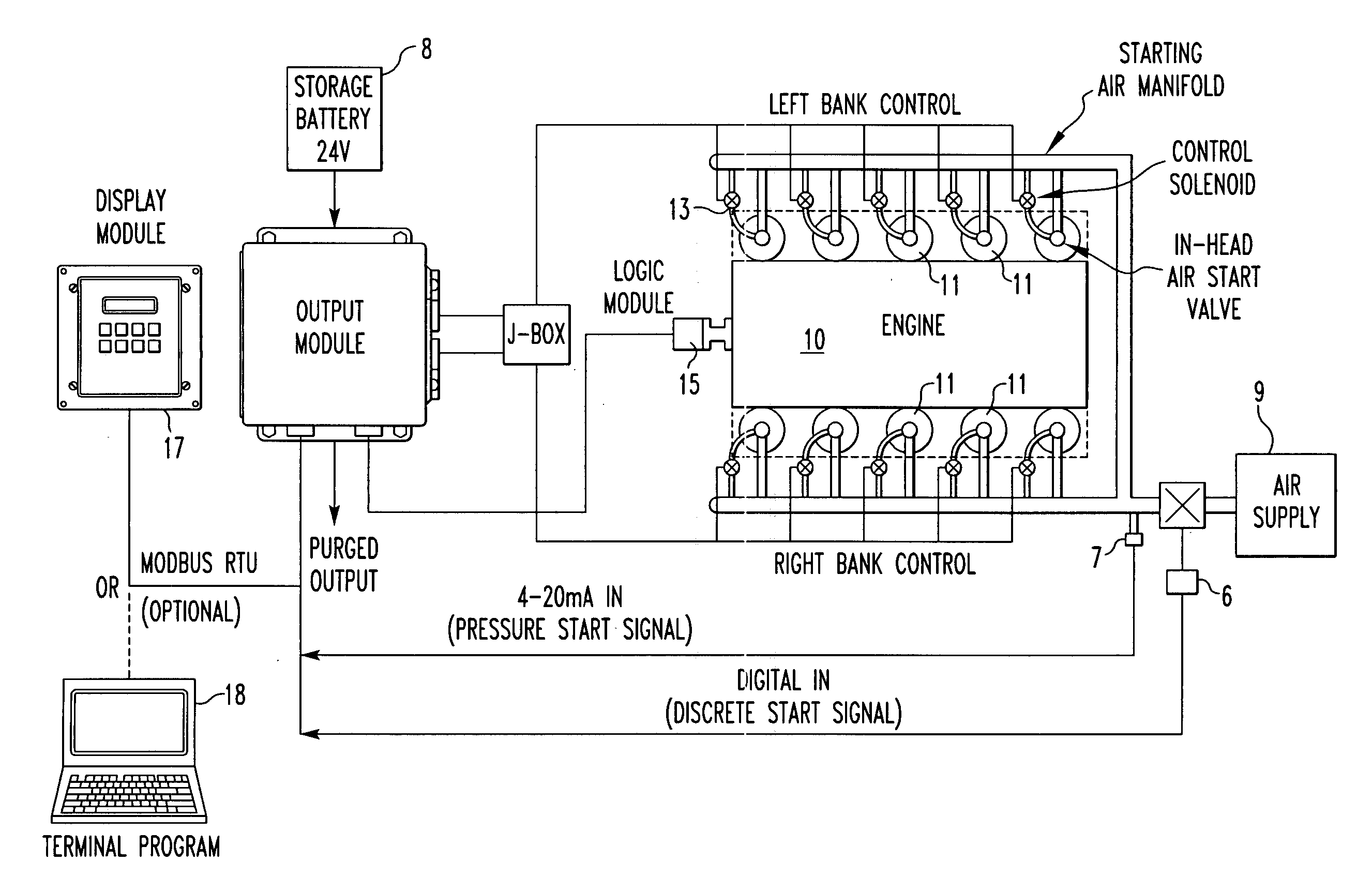
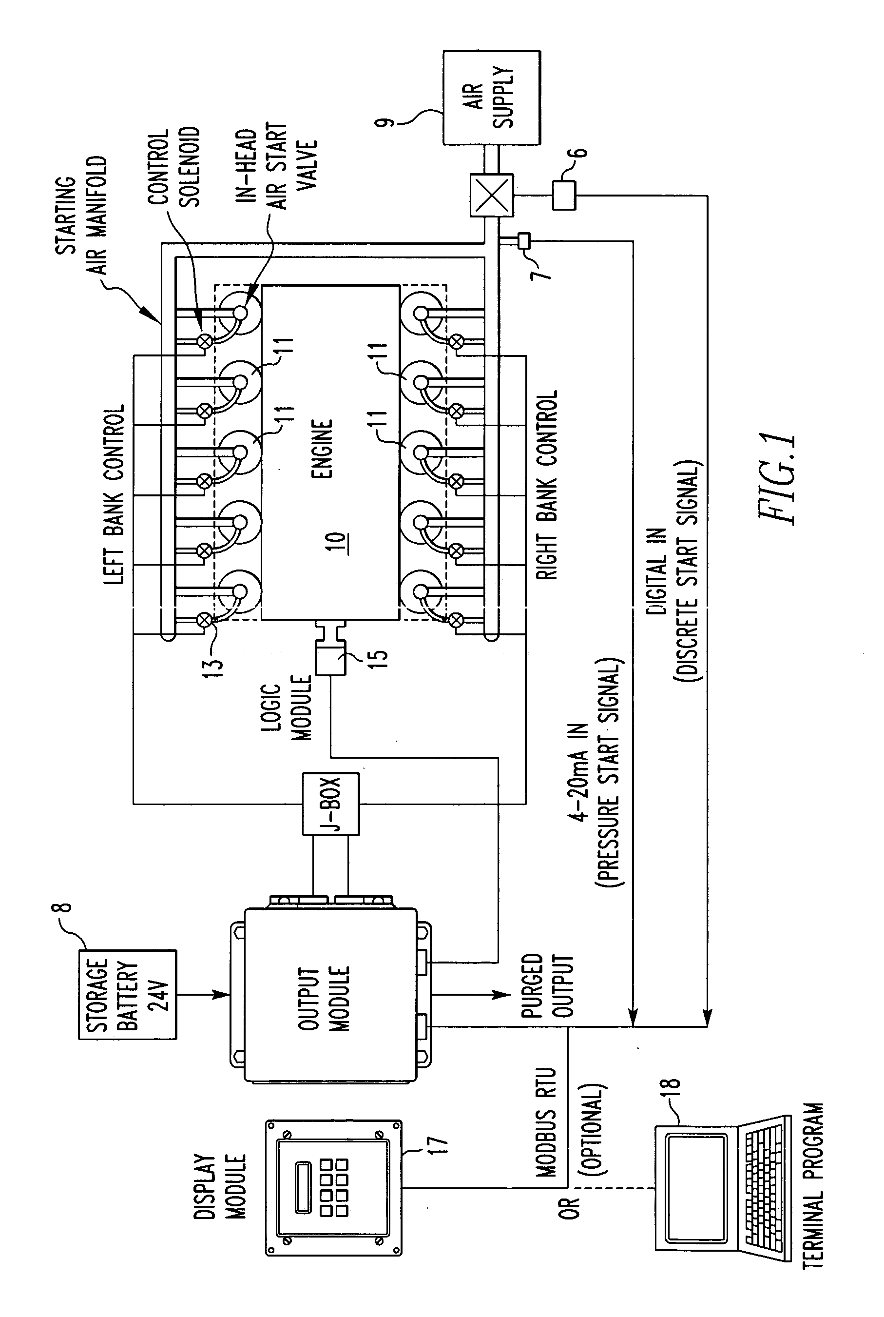
[0036]FIG. 1 schematically illustrates a ten-cylinder internal combustion engine 10 with two banks of five cylinders. Located in each cylinder head is an in-head air start valve 11 which is actuated with a pilot valve 13. A compressed air reservoir 9 is connected to a manifold 12 that supplies compressed air to both the pilot valves 13 and the in-head air start valves 11. The in-head air start valves 11 are pressure-operated check valves and will not open if the pressure in the cylinder exceeds the reservoir pressure. A piston is provided in each cylinder in the known manner and is connected to the crankshaft of the engine. When compressed air is admitted by an in-head air start valve 11 beginning when the piston is near top dead center (TDC) and during a portion of the power stroke, the piston is forced toward the crankshaft causing rotation of the crankshaft. By opening and closing the in-head air start valves 11 in the proper sequence, the cranking speed (start-up speed) of the e...


PUM


Abstract

An in-head compressed air start-up system for an internal combustion engine comprises an absolute angular position detector for the crankshaft outputting an electrical signal indicative of the angular position, a computer for storing a table of the firing order of the cylinders and the angular position of the crankshaft at which each piston reaches a desired angular position relative to top dead center (TDC), wherein the computer means compares the signal indicative of angular position of the crankshaft to the firing order table and generates a plurality of signals sequentially open and close solenoid valves to cause rotation of the crankshaft.

Description

BACKGROUND OF THE INVENTION [0001] 1. Field of the Invention [0002] The present invention relates to a starting system for large internal combustion engines, for example, large natural gas fueled engines, provided with associated air compressors and in-head air starting valves. [0003] 2. Description of Related Art [0004] It is known in the art to provide starting systems for multi-cylinder internal combustion engines, for example, those located at remote locations, by use of compressed air stored at the site of the internal combustion engine. The compressed air may be restored when the internal combustion engine is running by a compressor driven by the engine. These systems direct the compressed air to one or more cylinders of the engine at the proper crank angle and in the proper order to drive rotation of the engine crankshaft to a start-up speed. [0005] Some prior art systems are entirely mechanical and comprise a compressed air distributor that is driven by the camshaft. A rotat...

Claims


Application Information

Patent Timeline
Patent Type & Authority Applications(United States)
IPC IPC(8): F02N9/04
CPCF02N9/04
Inventor LEPLEY, JOSEPH M.KLEINFELDER, GARY A.
Owner ALTRONIC
Why Eureka
Try Eureka