Moving body

a moving body and body technology, applied in the field of moving bodies, can solve the problems of releasing water to swash on pedestrians, troublesome subsequent and nearby vehicles, etc., and achieve the effect of restrainting the splashing of discharged water

Inactive Publication Date: 2007-01-11
TOYOTA JIDOSHA KK
View PDF5 Cites 26 Cited by
  • Summary
  • Abstract
  • Description
  • Claims
  • Application Information

AI Technical Summary

Benefits of technology

[0065] The tenth moving body of the invention has the water tank located in the exhaust system and the drain formed in the front portion of the moving body to discharge the water from the water tank. The tenth moving body of the invention may have insufficient effects of restraining the water discharge under the condition of the high-speed motion of the moving body. As mentioned above, the presence of the front-facing opening restricts water discharge under acceleration of the moving body, while facilitating water discharge under deceleration of the moving body. During a general run, the moving body often repeats acceleration and deceleration and does not continue running at a fixed cruising speed. The arrangement of facilitating the water discharge under deceleration and restraining the water discharge under acceleration thus reduces scatter of the discharged water during a run of the moving body to the level that does not interfere with smooth driving of subsequent and nearby moving bodies. Here a typical example of the moving body is a vehicle.
[0066] In the tenth moving body of the invention, the water tank and the drain may be located inside the moving body to discharge water out of the moving body through an exhaust pipe. In one preferable embodiment of the tenth moving body of the invention, the drain has an opening at a position and orientation to make a ram pressure produced by motion of the moving body act in a direction of restricting discharge of the water. In one preferable structure of this embodiment, the water tank is attached to the outside of the moving body. This structure ensures application of the ram pressure onto the drain. In another preferable structure of this embodiment, the water tank is located inside the moving body, whereas the drain is formed outside the moving body. Application of the ram pressure onto the drain restricts the water discharge under the condition of the high-speed motion of the moving body and thereby effectively restrains splash of the discharged water.

Problems solved by technology

Even when the water is released in such a manner that does not wet wheels to avoid a potential skid, the released water may cause some troubles on subsequent and nearby vehicles.
The release of the water in a lateral direction, however, may cause the released water to swash on a pedestrian on the road shoulder or a nearby building.

Method used


Image

  • Moving body
  • Moving body
  • Moving body

Examples


first embodiment

A. First Embodiment

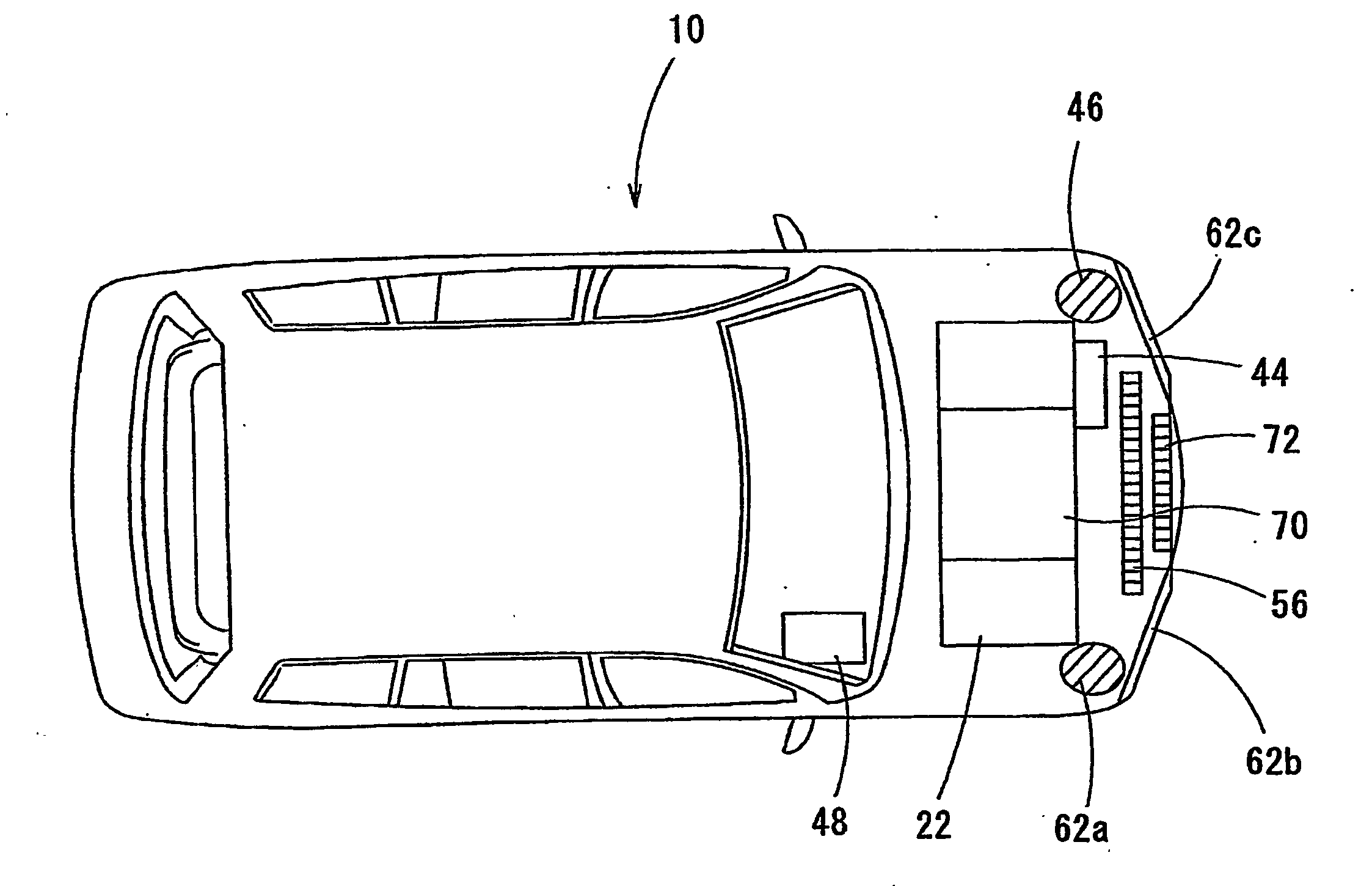
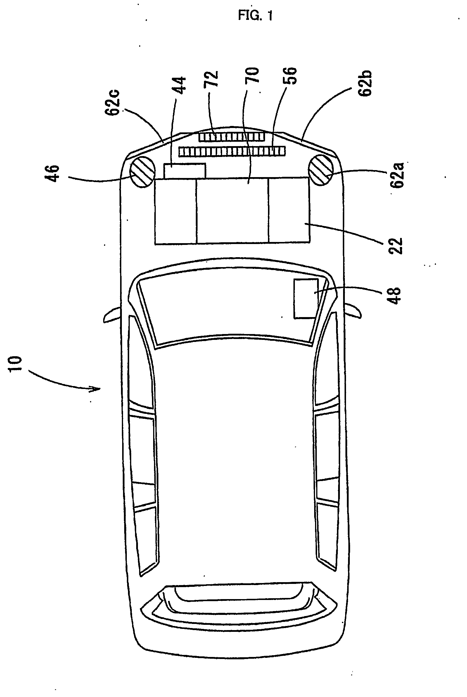
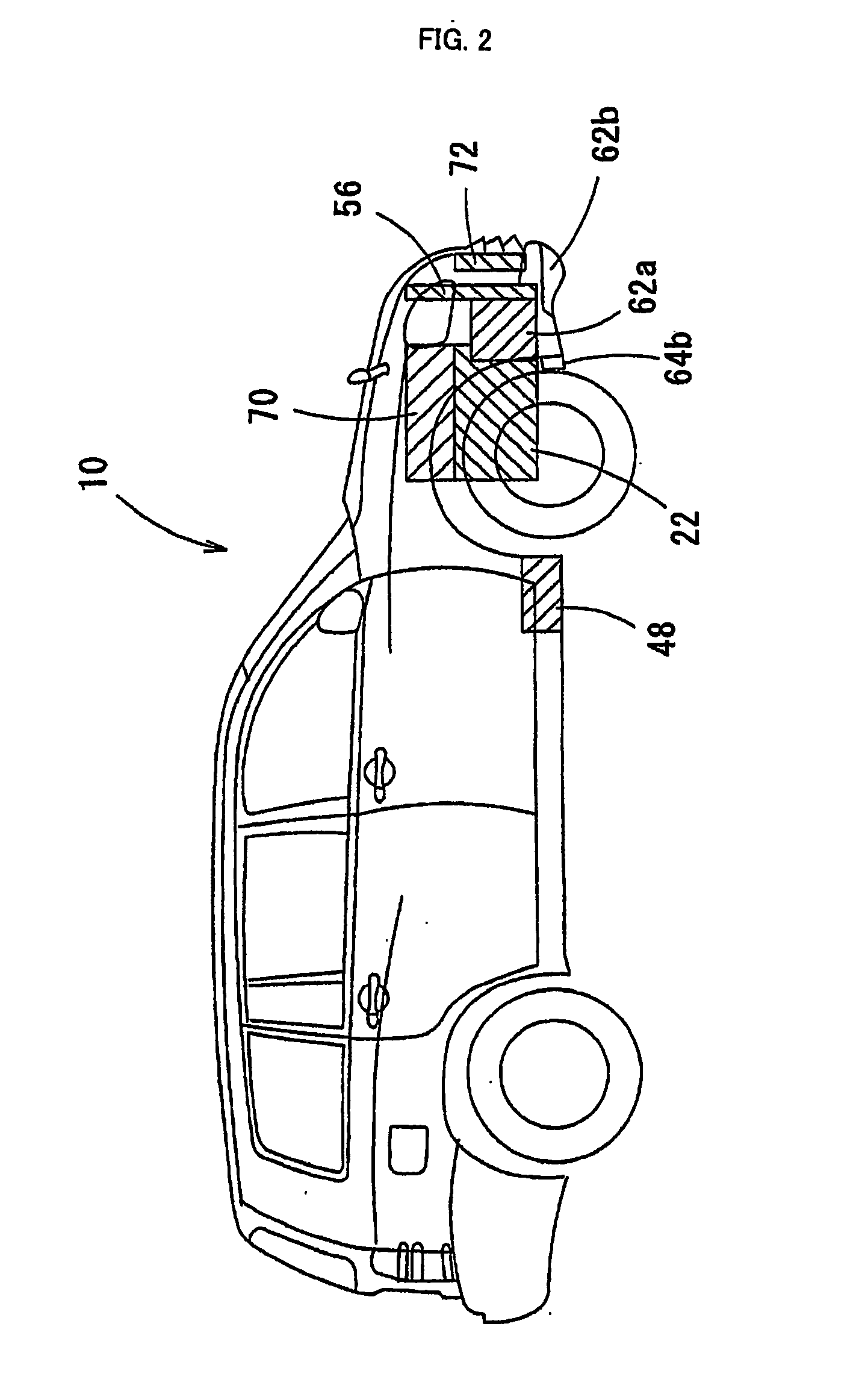
[0113]FIG. 1 is a plan view showing a plane layout of devices mounted on a fuel cell vehicle 10 in a first embodiment of the invention. FIG. 2 is a side view showing a side layout of the devices mounted on the fuel cell vehicle 10 of the first embodiment. FIG. 3 is a system diagram schematically showing the configuration of a fuel cell system 20 that includes a fuel cell stack 22 and is mounted on the fuel cell vehicle 10 of the first embodiment. For simplicity of explanation, the description first regards the configuration of the fuel cell system 20 with reference to the system diagram of FIG. 3 and then the layout of the respective devices included in the fuel cell system 20 with reference to FIGS. 1 and 2.

[0114] The fuel cell system 20 mounted on the fuel cell vehicle 10 of the first embodiment includes a fuel cell stack 22 or a stack of multiple layers of unit cells, each of which has two electrodes (a fuel electrode and an air electrode) arranged across a po...

second embodiment

B. Second Embodiment

[0127] A fuel cell vehicle 110 in a second embodiment of the invention is discussed below. FIG. 4 is a plan view showing a plane layout of a water outlet 164 in the fuel cell vehicle 110 of the second embodiment. FIG. 5 is a side view showing a side layout of devices mounted on the fuel cell vehicle 110 of the second embodiment. The fuel cell vehicle 110 of the second embodiment has similar structure to that of the fuel cell vehicle 10 of the first embodiment, except exclusion of the buffer tanks 62b and 62c, layout of the water outlet 164 for releasing the water accumulated in the buffer tank 62a, and addition of an air flow-guiding path 180 to guide the air flow to the vicinity of the water outlet 164. In order to avoid duplicated explanation, the like constituents of the fuel cell vehicle 110 of the second embodiment to those of the fuel cell vehicle 10 of the first embodiment are expressed by the like numerals and are omitted from the illustration and the det...

third embodiment

C. Third Embodiment

[0134] A fuel cell vehicle 210 in a third embodiment of the invention is discussed below. FIG. 8 shows the layout of a water outlet 264 in the fuel cell vehicle 210 of the third embodiment. The fuel cell vehicle 210 of the third embodiment has similar structure to that of the fuel cell vehicle 10 of the first embodiment, except exclusion of the buffer tanks 62b and 62c and layout of the water outlet 264 for releasing the water accumulated in the buffer tank 62a. In order to avoid duplicated explanation, the like constituents of the fuel cell vehicle 210 of the third embodiment to those of the fuel cell vehicle 10 of the first embodiment are expressed by the like numerals and are omitted from the illustration and the detailed description.

[0135] In the fuel cell vehicle 210 of the third embodiment, the water outlet 264 connected to the buffer tank 62a by a conduit pipe 263 is attached to a lower arm 282 by means of an air dam 283. The lower arm 282 works as an unde...


PUM

PropertyMeasurementUnit
angleaaaaaaaaaa
angleaaaaaaaaaa
angleaaaaaaaaaa

Abstract

In a fuel cell system 20 mounted on a fuel cell vehicle of the invention, water separated by a gas-liquid separator 38 included in a hydrogen supply system and by a gas-liquid separator 48 included in an air supply discharge system 40 is temporarily accumulated in buffer tanks 62a through 62c, which are set inside a front fender or inside a front bumper of the vehicle. The accumulated water is released from water outlets 64b and 64c located forward and backward a front wheel of the vehicle having relatively little potential effects of vehicle wind or air flow caused by motion of the vehicle. For the purpose of reducing the potential effects of the vehicle wind on the released water, the fuel cell vehicle may have an air flow path that makes the released water flown obliquely backward the vehicle by the air flow or form an air curtain of exhaust gas or the air ahead of the released water. This arrangement effectively restricts the released water from being scattered by and swirled on the vehicle wind and thereby prevents potential troubles such that the released water is scattered on other vehicles running on the side and behind.

Description

TECHNICAL FIELD [0001] The present invention relates to a moving body. Specifically, the invention relates to a moving body with fuel cells that are mounted thereon as a power source and generate electric power with production of water as a by-product BACKGROUND ART [0002] One example of proposed moving bodies is a motorcycle that releases water produced by fuel sells on the side of the vehicle (see, for example, Japanese Patent Laid-Open Gazette No. 2001-313056). Release of the water produced by the fuel cells on the side of the vehicle prevents potential troubles caused by splash of the water on wheels, for example, a skid of the wheels. [0003] A proposed technique to reduce the concentration of remaining hydrogen contained in exhaust gas from the fuel cells provides a baffle plate in the vicinity of an outlet of an exhaust pipe to accelerate diffusion of the exhaust gas (see, for example, Japanese Patent Laid-Open Gazette No. 2002-289237). Various techniques may be applied to rel...

Claims


Application Information

Patent Timeline
Patent Type & Authority Applications(United States)
IPC IPC(8): B01D35/00B60R16/08B60K1/00B60K1/04B60K8/00B60K13/04B60L11/18B60R19/48B62D37/02H01M8/00H01M8/04
CPCB60K1/00B60K1/04B60K13/04B60K2001/005Y02E60/50H01M2250/20Y02T90/32H01M8/04291H01M8/04156B60L58/30B60L50/70Y02T90/40
Inventor YOSHIDA, NAOHIROKONDO, TOSHIYUKIHIBINO, MASAHIKOYUMITA, OSAMUFUNAYAMA, YOSHIHIRO
Owner TOYOTA JIDOSHA KK
Why Eureka
Try Eureka