Method of manufacturing stator unit, and motor using the stator

a stator unit and stator technology, applied in the direction of positive displacement liquid engines, magnets, piston pumps, etc., can solve the problems of difficult mechanization (automation) of the twining process of the wire, the diameter of the wire used for the small motor is so small, and the needle of the wire-winding machine cannot be easily placed therebetween, so as to facilitate the twining process and prevent the open circuit of the wire

Active Publication Date: 2007-01-11
NIDEC CORP
View PDF2 Cites 17 Cited by
  • Summary
  • Abstract
  • Description
  • Claims
  • Application Information

AI Technical Summary

Benefits of technology

[0006] Preferred embodiments of the present invention provide a stator unit and a method of manufacturing the stator unit which facilitate manufacturing of the stator unit, especially facilitate the process of twining the wire from the coil to the terminal pin with preventing the open circuit of the wire.
[0007] In a stator unit according to one preferred embodiment of the present invention, a plurality of teeth and a plurality of terminal pins are axially spaced manner such that a needle of a wire-winding machine can be placed therebetween. After a plurality of coils are formed by winding wires around the plurality of teeth with the wire-winding machine, the wires from the coils are easily twined and connected to the terminal pins. Then the terminal pins are moved along a guide portion to bring it to the coils. Therefore, the manufacturing of the stator unit may be automated with preventing the wire from being cut, and the manufacturing of the stator unit may be facilitated.
[0008] According to another preferred embodiment of the present invention, in the manufacturing method of the stator unit, the terminal pins may be brought close the coils with rotating the terminal pins into a circumferential direction, centering on the center axis, along the outer side face of the sleeve housing. As a result, the terminal pins are approximated to the coils without applying unnecessary tension on the wires. Therefore, it is possible to make the motor thin and to prevent the wire from being cut.

Problems solved by technology

In such a small motor, the space between the pin to which the wire is twined and such as the stator core, the coil and the circuit board is so narrow that the needle of the wire-winding machine can not be easily placed therebetween.
Therefore, it is difficult to mechanize (automate) the twining process of the wire.
In addition, the wires used for the small motor have so small diameters that they may cut during the process of attaching the wires to the circuit board.

Method used


Image

  • Method of manufacturing stator unit, and motor using the stator
  • Method of manufacturing stator unit, and motor using the stator
  • Method of manufacturing stator unit, and motor using the stator

Examples


first preferred embodiment

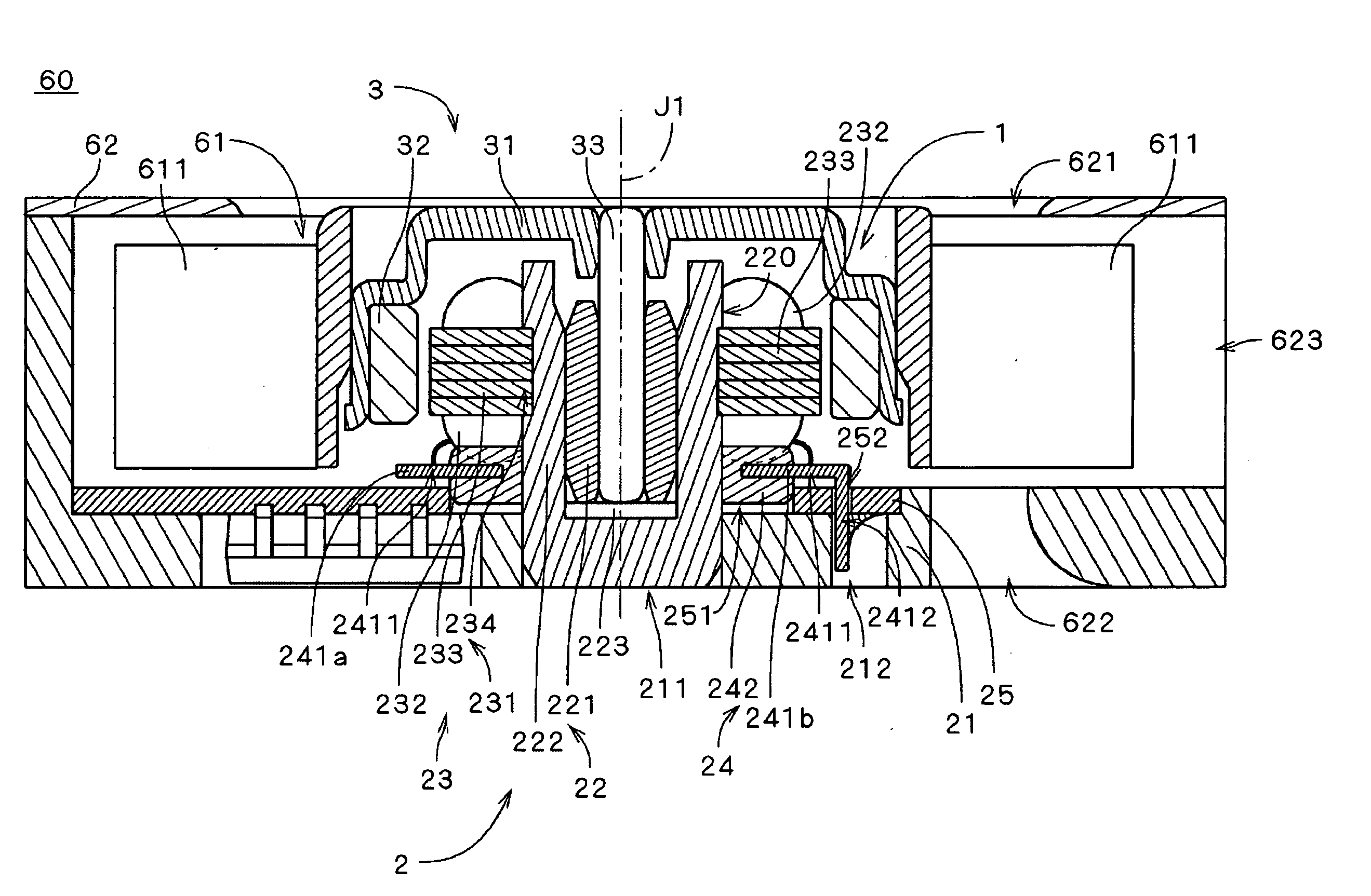
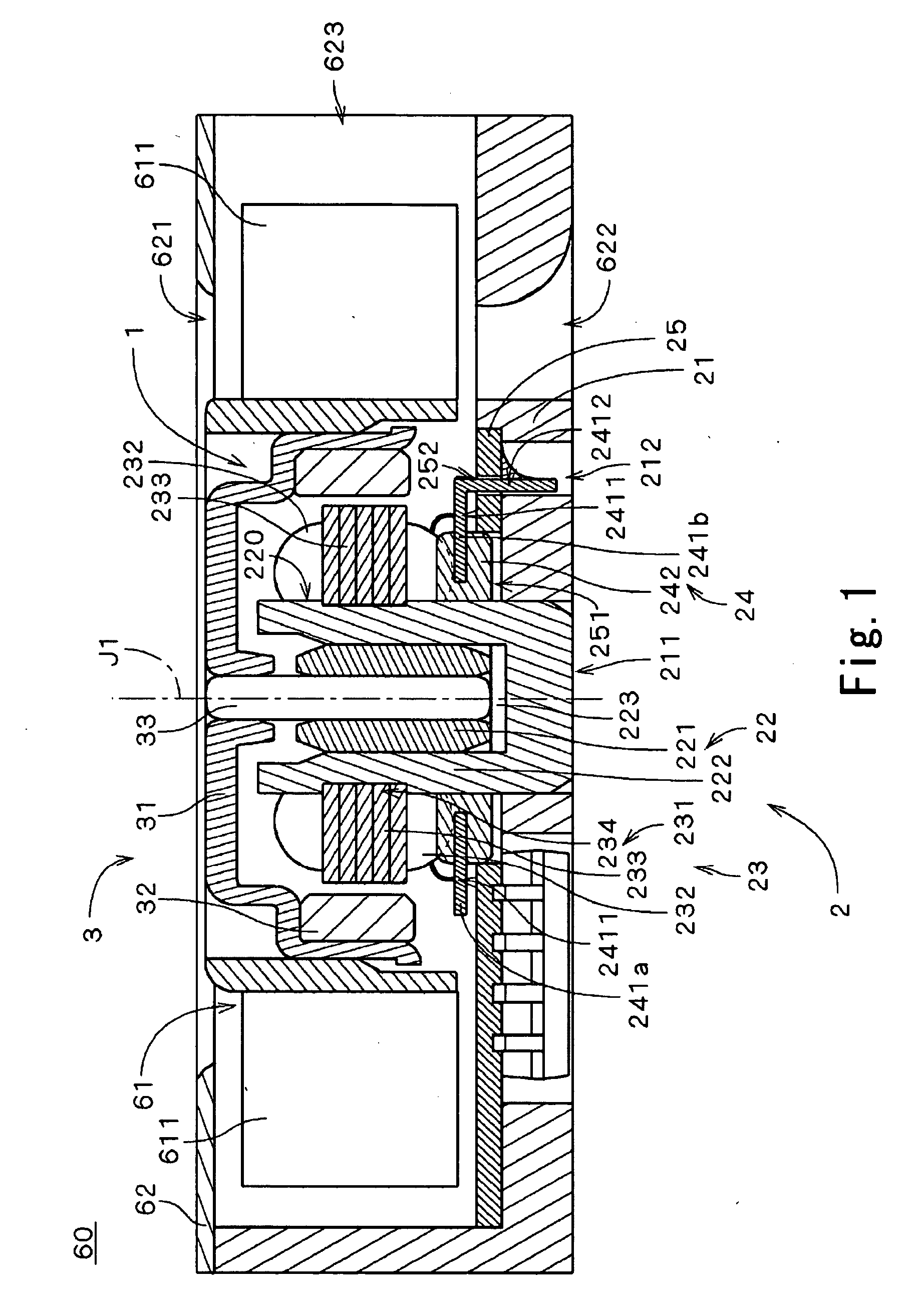
[0024]FIG. 1 is a vertical sectional view of an electrically powered motor 1 along a plane including a center axis J1, illustrating an internal configuration of a centrifugal fan 60 according to a first preferred embodiment of the present invention. The centrifugal fan 60 is, for example, used for an air-cooling fan for an electronic device and includes an impeller portion 61, a small motor 1 and a housing 62.

[0025] The impeller portion 61 rotates and generates air-flow. The impeller portion 61 is attached to the motor 1 and rotated with centering on the center axis J1. The housing 62 surrounds the impeller portion 61 and the motor 1 and defines a passage of the air-flow. Meanwhile, the housing 62 controls the air-flow generated by the rotation of the impeller portion 61 and air is sent forth therethrough.

[0026] As shown in FIG. 1, the motor 1 is an outer rotor motor, and includes a stator unit 2 which is a stationary assembly and a rotor unit 3 which is a rotatable assembly. Via ...

second embodiment

of the Present Invention

[0080] Next, a micro-motor 1a according to a second preferred embodiment of the present invention will be explained. FIG. 9 is a cross sectional view illustrating the motor 1a. As shown in FIG. 9, the motor 1a includes independent terminal pins 241c which are different in their shape from those illustrated in FIGS. 1 and 3. The rest of the configurations are the same as those illustrated in FIGS. 1 to 3, and are labeled with the same reference marks in the explanation that follows.

[0081] As indicated in FIG. 9, the motor 1a includes the stator unit 2 and the rotor unit 3. The rotor unit 3 is rotatably supported on the stator unit 2, with the center axis J1 as center, via a bearing mechanism employing hydrodynamic pressure by the agency of lubricating oil. The configuration of the bearing mechanism of motor 1a is the same as that described in the first preferred embodiment of the present invention. The rotor unit 3 includes the rotor hub 31 and the shaft 33, ...

third preferred embodiment

[0101] Next, a micro-motor 1b according to a third preferred embodiment of the present invention will be explained. FIG. 10 is a cross sectional view illustrating the motor 1b. As shown in FIG. 10, the motor 1b includes the common terminal pins 241d and independent terminal pins 241e which are different in their shape from those illustrated in FIGS. 1 and 3. The rest of the configurations are the same as those illustrated in FIGS. 1 to 3, and are labeled with the same reference marks in the explanation that follows.

[0102] As shown in FIG. 10, in the terminal 24 of the motor 1b, three terminal pins 241d and three independent terminal pins 241c, which are electrically connected to the coils 232, are provided on the base-side portions of the plurality of the coils 232.

[0103] Each of a plurality of terminal pins 241 (i.e., common terminal pins 241d and independent terminal pins 241e) extends in the radial direction centering on the center axis J1 and includes the wire connecting porti...


PUM

PropertyMeasurementUnit
diameteraaaaaaaaaa
diameteraaaaaaaaaa
axial distanceaaaaaaaaaa

Abstract

In manufacturing of the stator unit 2 according to one preferred embodiment of the present invention, a plurality of terminal pins are arranged in an axially spaced manner from a plurality of the coils during a twining process of the wires from the coils 232 to the terminal pins 241. Then, after the wire is twined to the terminal pins, the terminal pins connected to the coils are moved along the outer side face of the sleeve housing, functioning to as a guide portion for the terminal pins. By virtue of the configuration, the terminal pins 241 may be approximated to the coils without applying the tension on wire, and the stator unit may be made thin with preventing the open circuit of the wires.

Description

FIELD OF THE INVENTION [0001] The present invention generally relates a method of manufacturing a stator unit and an electrically powered motor using the stator unit. BACKGROUND OF THE INVENTION [0002] Conventionally, axial fans and centrifugal fans used for cooling electric devices are driven by electrically powered motors. Such a motor includes a rotor unit having a rotor magnet around a center axis of the motor and a stator unit having a stator generating torque between the rotor unit and the stator unit. The stator unit includes a plurality of coils formed by winding wires around a plurality of teeth. The ends of the wires wound around the teeth are electrically connected to a circuit board such that the electricity is provided to the stator. [0003] There are various methods of connecting the ends of the wires forming the coils and the circuit board. In a publicly available example of such method, firstly, a conductive pin axially protruding from the bottom side of the stator to...

Claims


Application Information

Patent Timeline
Patent Type & Authority Applications(United States)
IPC IPC(8): H02K7/00H02K11/00F04B17/00
CPCH02K1/187Y10T29/53143H02K5/1675H02K15/0056H02K15/0062H02K15/0075H02K15/022H02K15/095H02K21/22F04D25/0646Y10T29/49071Y10T29/49012Y10T29/49011Y10T29/49009H02K3/522H02K15/0068
Inventor TESHIMA, HIROYOSHITAKESHITA, KAZUMIKONISHI, HIDEAKIIDA, KIYOTOTAKAOKA, TSUKASA
Owner NIDEC CORP
Why Eureka
Try Eureka