Semiconductor devices
- Summary
- Abstract
- Description
- Claims
- Application Information
AI Technical Summary
Benefits of technology
Problems solved by technology
Method used
Image
Examples
embodiment 1
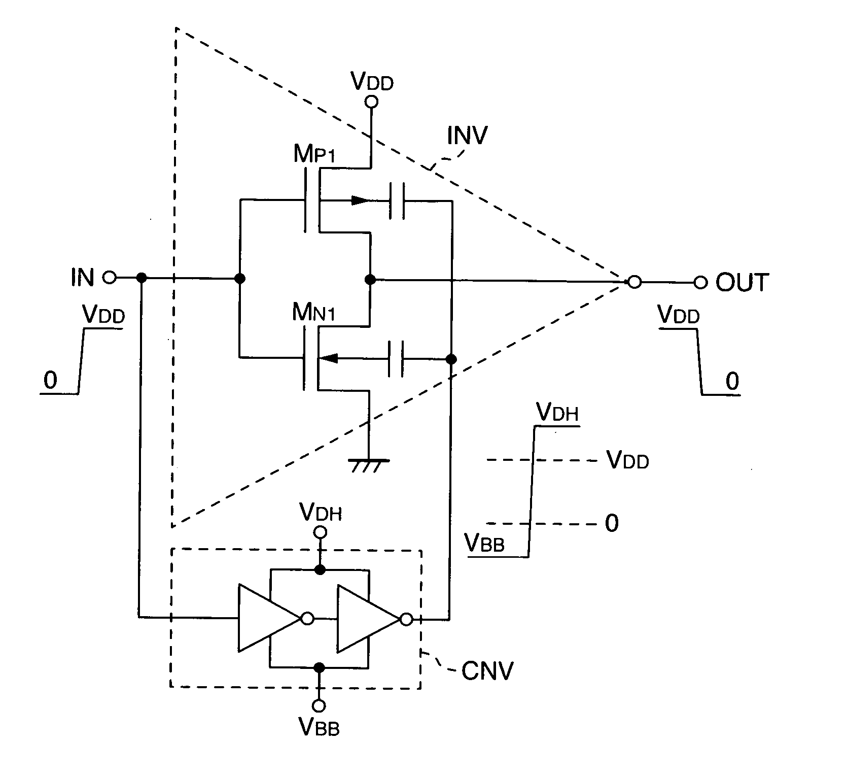
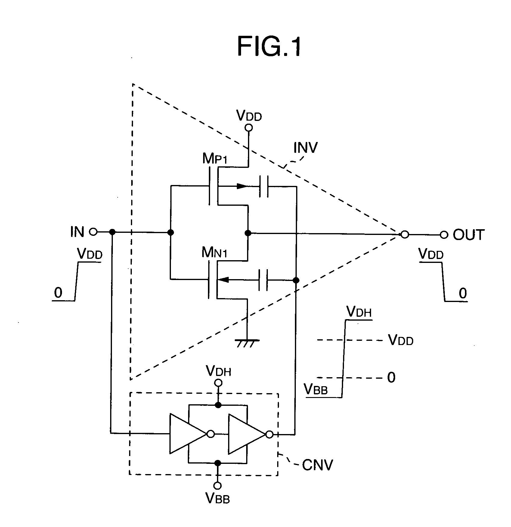
[0027]FIG. 1 illustrates a CMOS inverter circuit which is a first embodiment of the present invention. A first circuit includes, e.g., an inverter INV, and a second circuit includes, e.g., a converter CNV for controlling well voltages with large voltage amplitudes. The second circuit is a sub-circuit. This sub-circuit drives comparatively small well capacities of MOSTs within the first circuit, and thus is easy to design into small-size, high-speed, and low power-consumption implementation. In contrast thereto, the first circuit is a main-circuit. This main-circuit must generically drive large load capacities, and thus cannot help being formed into large-area, low-speed, and large power-consumption implementation. Consequently, adding the second circuit to the first one results in exertion of only a small influence on the entire area, speed, and power consumption.
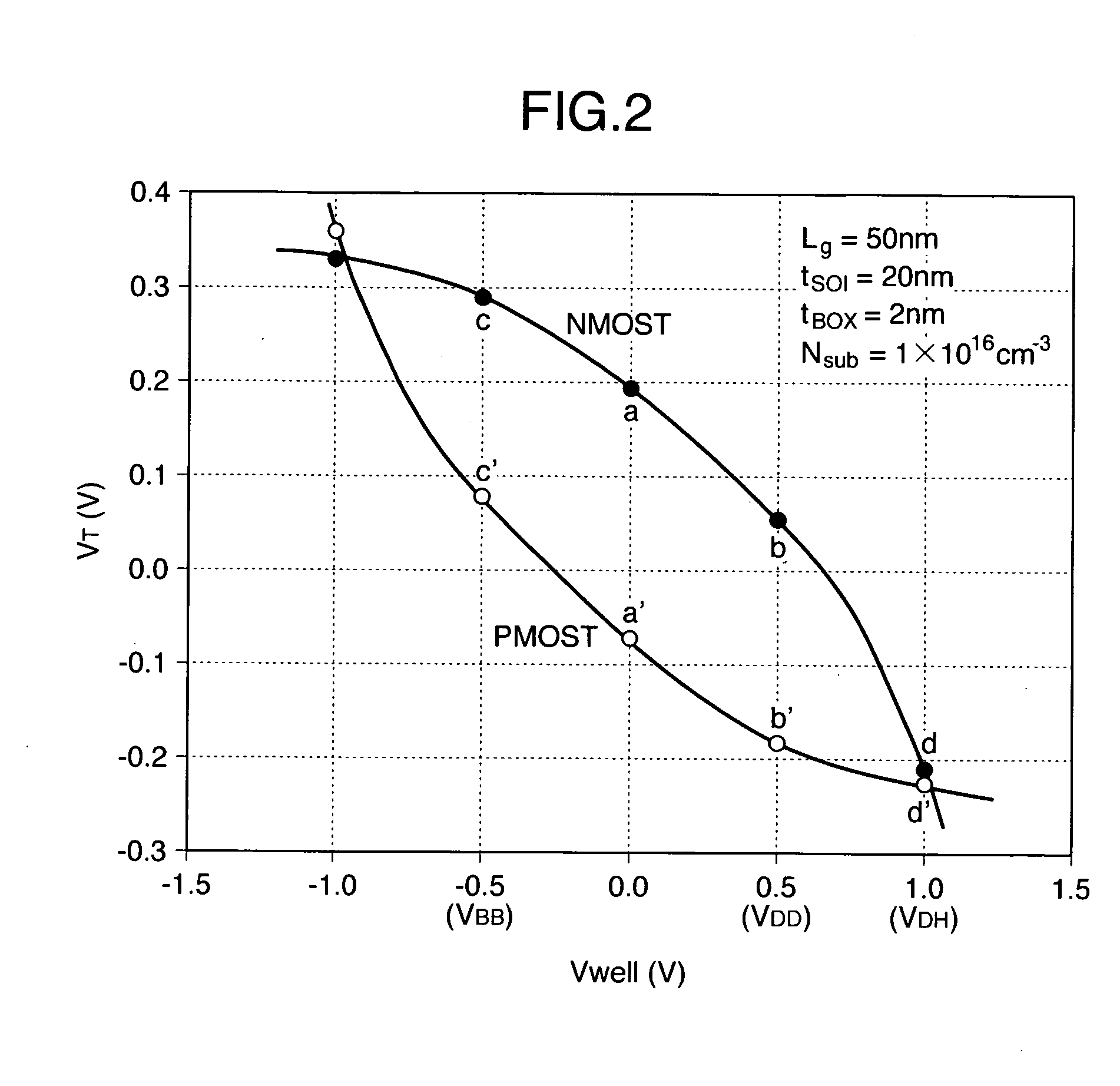
[0028] A PMOST (MP1) and an NMOST (MN1) are the FD-SOI MOST illustrated in FIG. 11 and FIG. 12. FIG. 2 illustrates the r...
embodiment 2
[0041]FIG. 4A, FIG. 4B, and FIG. 4C illustrate power-supply switches to which a MOST whose well is driven with a large voltage amplitude is applied, and which are then made small-sized. Here, a first circuit is a power-supply switch, and a second circuit is an internal core circuit (CORE). The operating voltage for the internal core circuit is small, and accordingly the threshold voltage VT of the MOST is also small. This results in flowing of a large sub-threshold current therein. FIG. 4A illustrates the following circuit: Using the PMOST (MP), power-supply VDD for the internal core circuit is cut off from the internal core circuit during an unnecessary time-zone, thereby cutting the sub-threshold current in the internal core circuit. During the unnecessary time-zone, e.g., a time-period such as standby time or sleep mode, switching the PMOST completely OFF requires that VT of the PMOST be made larger. On the other hand, during a time-zone in which the internal core circuit operate...
embodiment 3
[0043]FIG. 5A illustrates an embodiment where the present invention is applied to a MOST switch (i.e., first circuit) and a repetition-circuit block (BLK) (i.e., second circuit). Here, this repetition-circuit block is, e.g., a word-driver block of memory. Each MOST included therein is the FD-SOI MOST. The respective sources of output PMOSTs (MW) of inverters are collectively connected to a single common source line PWL. Moreover, the PWL is connected to power-supply voltage VDD via the switch MOST (MP). At the time of selection for an inverter, the switch MOST (MP) is switched ON, and the input voltage into one inverter INV out of the n inverters within the block BLK is made equal to 0 V. This operation selects the one inverter INV, thus selecting and driving the corresponding one word line from among n word lines (i.e., WL0, . . . , WLn-1). On the other hand, at the time of the non-selection, the gate voltage of MP is made equal to VDD to switch MP OFF. Also, the input voltages int...
PUM
 Abstract
Description
Claims
Application Information
 - R&D
- Intellectual Property
- Life Sciences
- Materials
- Tech Scout
- Unparalleled Data Quality
- Higher Quality Content
- 60% Fewer Hallucinations
Browse by: Latest US Patents, China's latest patents, Technical Efficacy Thesaurus, Application Domain, Technology Topic, Popular Technical Reports.
© 2025 PatSnap. All rights reserved.Legal|Privacy policy|Modern Slavery Act Transparency Statement|Sitemap|About US| Contact US: help@patsnap.com


