Transport layer relay method, transport layer relay device, and program

a relay device and transport layer technology, applied in the field of communication systems, can solve the problems of poor communication efficiency, inability to realize efficient communication, and cost of a multiplicity of devices, and achieve the effect of redistributing bandwidth, low cost, and redistributing bandwidth

Active Publication Date: 2007-01-11
NEC CORP
View PDF8 Cites 150 Cited by
  • Summary
  • Abstract
  • Description
  • Claims
  • Application Information

AI Technical Summary

Benefits of technology

[0027] The first merit of the present invention is the ability to secure a desired effective rate for a particular set of transport layer connections between a plurality of terminals and to redistribute the bandwidth among this set of connections at low cost.
[0028] The second merit of the present invention is the ability to secure, for a particular set of transport layer connections between a plurality of terminals, an effective rate that confers priorities to other transport layer connections and to redistribute the bandwidth among this set of connections at low cost.
[0029] The third merit of the present invention is the ability to redistribute a particular effective rate for a particular set of transport layer connections between a plurality of terminals amon

Problems solved by technology

It was therefore not possible to realize efficient communication in which high bandwidth is allotted to specific connections or in which bandwidth is circulated among connections.
As a result, communication efficiency was poor immediately after the establishment of a connection.
As the first problem of the methods of the prior art, in the first example of the prior art, the control of priority in packet scheduling and the control of fixed bandwidth allotment must be carried out in all routers on the communication path of transceiving terminals, and as a consequence, the need arises for the replacement of a multiplicity of routers, and this results in the cost of a multiplicity of devices and the inconvenience entailed for replacing the devices.
As the second problem of the prior art, in the second and third examples of the prior art, control of the throughput of all connections being observed is realized by using the congestio

Method used


Image

  • Transport layer relay method, transport layer relay device, and program
  • Transport layer relay method, transport layer relay device, and program
  • Transport layer relay method, transport layer relay device, and program

Examples


first embodiment

of the Present Invention

Explanation of the Configuration of the First Embodiment of the Present Invention

[0064] Explanation next regards the details of the configuration of the first embodiment of the present invention with reference to the figures.

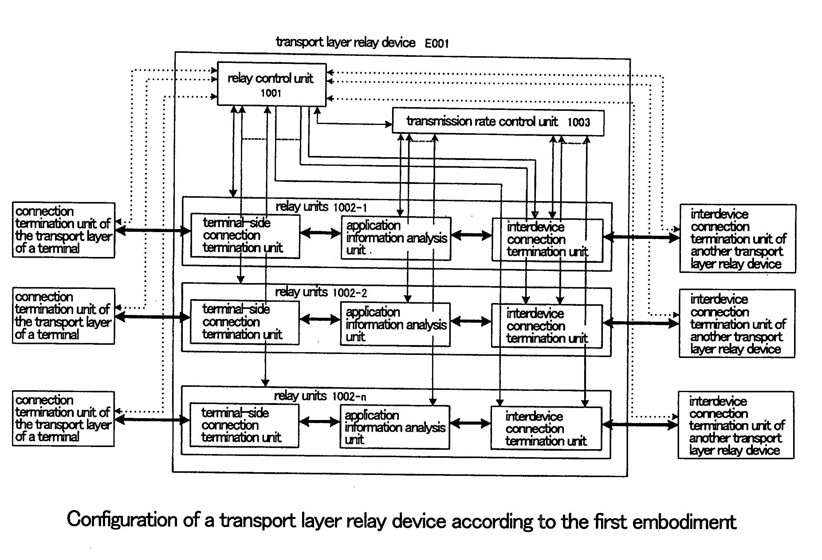
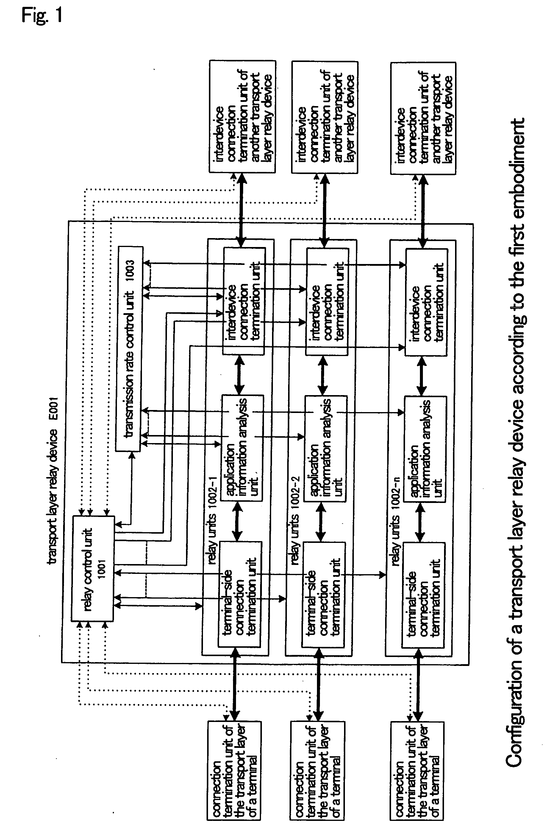
[0065]FIG. 1 is a block diagram of the interior of transport layer relay device E001 of the first embodiment of the present invention. Transport layer relay device E001 includes internally: relay control unit 1001, relay units 1002-1-1002-n, and transmission rate control unit 1003. Transport layer relay device E001 can be realized by a computer. When realized by a computer, a program for realizing relay control unit 1001, relay units 1002-1-1002-n, and transmission rate control unit 1003 is recorded on a disk, a semiconductor memory, or other recording medium. This program is read by a computer, and through the control of the operations of the computer, relay control unit 1001, relay units 1002-1-1002-n, and transmission rate control un...

second embodiment

of the Present Invention

[0135] Explanation of the Configuration

[0136] Explanation next regards the details of the configuration of the second embodiment of the present invention with reference to the accompanying figures.

[0137]FIG. 5 is a block diagram showing the interior of transport layer relay device E002 of the second embodiment of the present invention. This transport layer relay device E002 differs from transport layer relay device E001 of the first embodiment of the present invention only in the addition of network condition estimation unit 2004 and the connection to transmission rate control unit 2003. The operations of relay control unit 1001, relay units 1002-1-1002-n, the terminal-side connection termination units that are inside the relay units, the application information analysis units, and interdevice connection termination units are the same as the operations of the equivalent components of transport layer relay device E001 of the first embodiment, and redundant e...

third embodiment

of the Present Invention

Explanation of the Configuration of the Third Embodiment of the Present Invention

[0182] The following explanation regards the details of the configuration of the third embodiment of the present invention with reference to the accompanying figures.

[0183]FIG. 8 is a block diagram of the interior of transport layer relay device E003 of the third embodiment of the present invention. Transport layer relay device E003 includes: relay control unit 3001, relay units 3002-1-3002-n, transmission rate control unit 3003, interdevice connection termination unit 3004, and MUX-DEMUX unit 3005. Transport layer relay device E003 can be realized by a computer. When transport layer relay device E003 is realized by a computer, a program for realizing relay control unit 3001, relay units 3002-1-3002-n, transmission rate control unit 3003, interdevice connection termination unit 3004, and MUX-DEMUX unit 3005 is recorded on a disk, semiconductor memory, or other recording medium....


PUM


Abstract

Relay units (1002-1-1002-n) terminate a plurality of transport layer connections from terminals in a transport layer and relay each of these connections to other transport layer connections (relay connections). A transmission rate control unit (1003) determines the total transmission rate of the relay connections according to the number of connections that are being relayed and network congestion conditions such that a desired effective rate is obtained, and moreover, allots the total transmission rate as transmission rates to each of relay units (1002-1-1002-n) in accordance with the results of the analysis of information of the applications being carried on the transport layer connections during relay.

Description

TECHNICAL FIELD [0001] The present invention relates to a communication system realized by means of packet switching, and more particularly to a technology for relaying connections of a protocol layer having a congestion control capability. BACKGROUND ART [0002] In the network protocol of an OSI reference model, the functions of a data communication network are broadly divided into a hierarchy of seven layers, these layers being, in order from the lowest, the physical layer, the data link layer, the network layer, the transport layer, the session layer, the presentation layer, and the application layer. In a packet network, when applications on terminals communicate data that extend over a plurality of packets, a virtual connection is extended between applications and the application data are sent over this connection. Such a connection is typically established using a protocol that is a higher layer than transport. In addition, among the protocols of the layer in which the connecti...

Claims


Application Information

Patent Timeline
IPC IPC(8): H04L12/26H04J1/16H04L12/46H04L13/08H04L47/41
CPCH04L47/40H04L47/10H04L47/431
Inventor KOBAYASHI, MASAYOSHI
Owner NEC CORP
Why Eureka
Try Eureka