
Continuous OLED coating machine

a coating machine and continuous technology, applied in the direction of vacuum evaporation coating, photomechanical equipment, instruments, etc., to achieve the effect of avoiding or reducing mask stockpiling and minimising the number of masks

Inactive Publication Date: 2007-01-11
APPLIED MATERIALS GMBH & CO KG
View PDF2 Cites 98 Cited by
  • Summary
  • Abstract
  • Description
  • Claims
  • Application Information

AI Technical Summary

Benefits of technology

[0011] At least one aspect of the invention is directed to create a coating machine or a device for especially continuous production of a substrate provided with organic electroluminescent materials (OLED), especially OLED displays, screens, panels or other OLED lighting elements, in which the disadvantages of the prior art are avoided and especially a simple and favourable possibility for mass production of OLED elements is provided, combined with a small space requirement and with allowance for high quality standards for the OLED products. In at least one version the corresponding device is easy to manufacture and the process easy to operate.
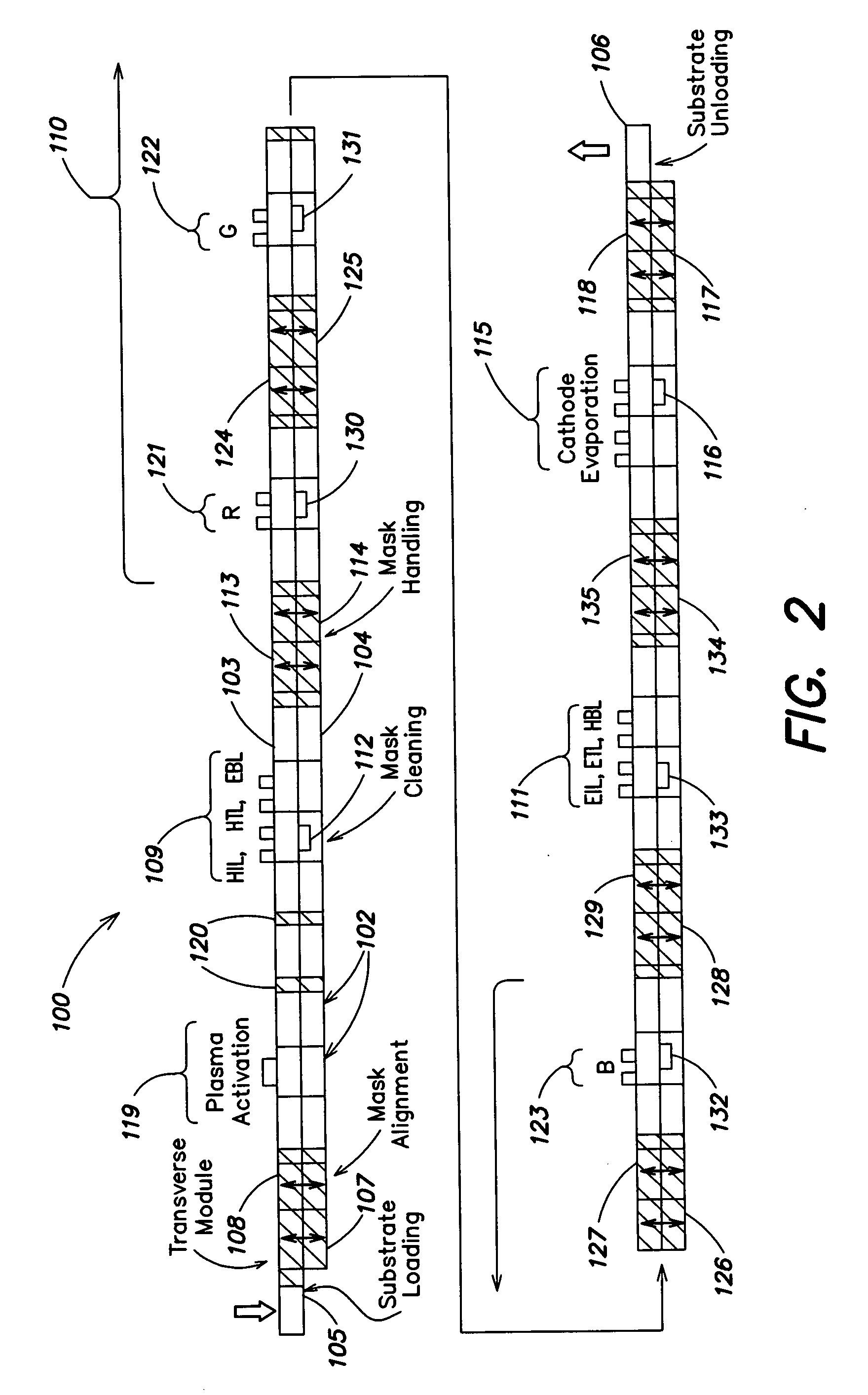
[0012] One aspect of the invention is characterised by the fact that the coating machine or device is constructed on the dual-chamber principle, i.e. that the entire vacuum space of the vacuum-coating machine is preferably divided into two parts along its longitudinal axis, with a first part of the vacuum space used to transport the carriers loaded with the substrates to be coated through the coating machine from the loading to the unloading station and the other, second part of the machine serving to return and clean the substrate carriers and especially the masks required for structuring. This has the advantage that a very compact machine with genuine continuous operation can be realized as a so-called in-line machine, in which stockpiling of both carriers and masks is largely avoided by guiding carriers and / or masks in endless loops, and the throughput and efficiency are substantially increased.
[0013] Furthermore, by virtue of the dual-chamber principle, simple construction and simple operation, especially also for the generation of the vacuum, are possible, with especially the dual chambers capable of being formed as all-round modules, such that corresponding process tools and other devices can be arranged in the corresponding dual-chamber modules, as required. This greatly facilitates conversion as well. Moreover, such a construction facilitates uninterrupted transport of substrates or carriers and / or masks for microstructuring the coatings in the vacuum. As a result, contamination of the carriers or masks by the environment is avoided.
[0014] Further, where necessary, lock chambers and / or lock devices and isolating devices can be provided between the individual chambers or chamber modules in order that specific areas may be sealed off to avoid contamination or in the event of partial venting of the machine.
[0016] In addition, preferably at least one transport branch may be provided in which the transport device for the substrate carrier and / or the transport arrangement for the masks is not formed as a continuous loop, but instead parallel transport sections in the same and / or opposite direction are provided in the dual chambers. This can be advantageous in the infeed and outfeed areas especially, since, in this way, both parts of the vacuum dual chambers can be used for transporting the substrates on the substrate carriers to and away from the mask-placement station, and as a result the efficiency can be greatly enhanced. Correspondingly, more substrates can be diverted in quick succession into the coating process, a fact which further increases the efficiency of the machine.
[0024] In at least one embodiment of a device, it is possible, given corresponding processes for production of OLED elements, during return transport to directly clean the masks or shadow masks required for structuring of the coatings and to avoid or reduce mask stockpiling as well as to minimise the number of necessary masks overall.

Problems solved by technology

Moreover, such a construction facilitates uninterrupted transport of substrates or carriers and / or masks for microstructuring the coatings in the vacuum.

Method used


Image

  • Continuous OLED coating machine
  • Continuous OLED coating machine
  • Continuous OLED coating machine

Examples


Embodiment Construction

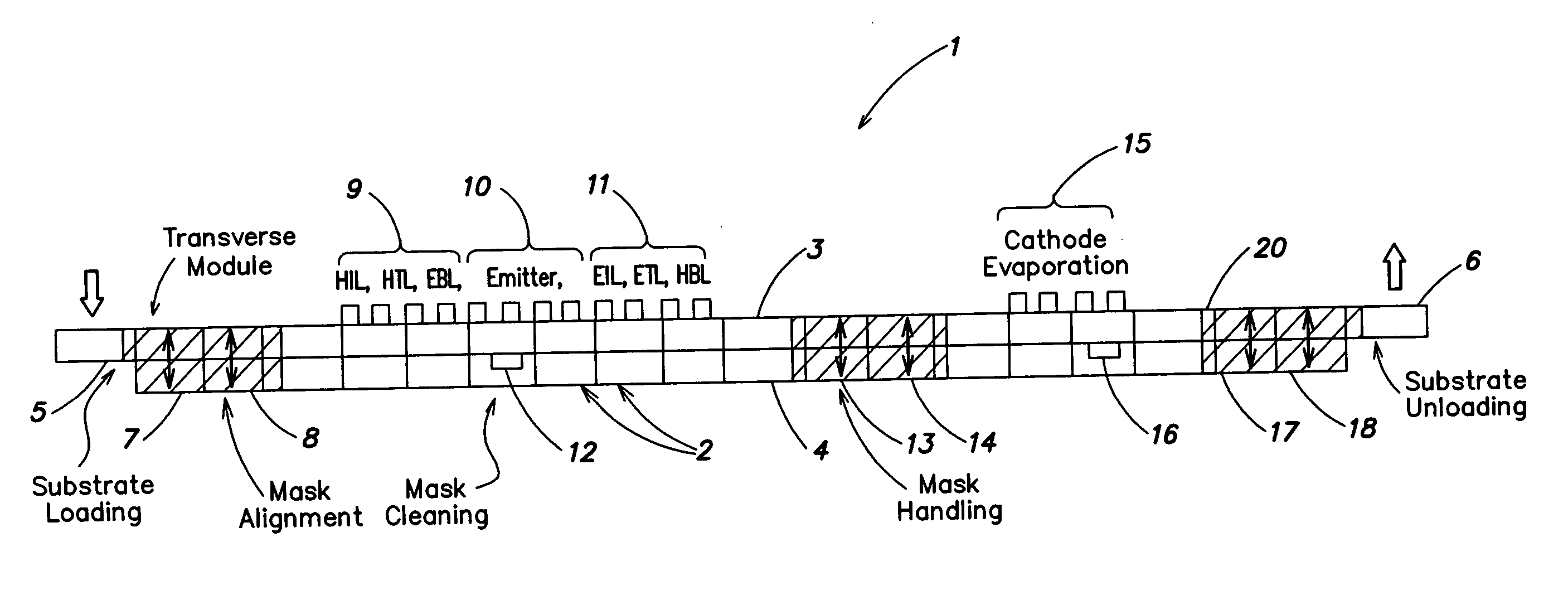
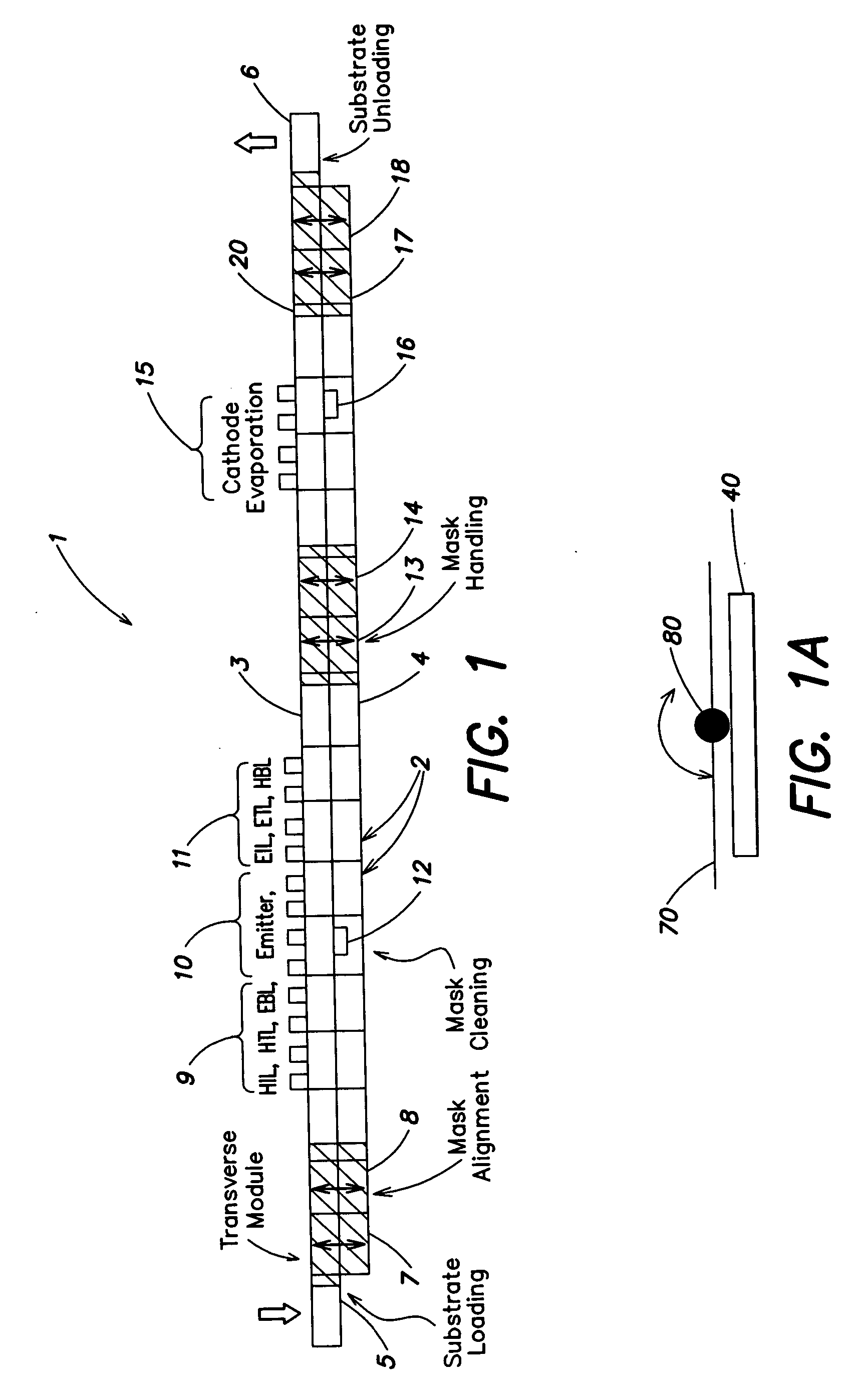
[0034]FIG. 1 shows a device in accordance with one embodiment of the invention configured for generating organic LEDs (OLED) that emit white light. Device 1 comprises a plurality of vacuum dual chambers 2 in succession, each of which is split into parts (halves) 3 and 4 and which form a vacuum space with their neighbouring chambers. Aside from the division of the vacuum space into the two parts 3 and 4 along the longitudinal axis of the device, the vacuum space is additionally subdivided in the embodiment shown in FIG. 1 by mask-placement station 14 and mask-removal stations 13 into two areas, with a subdivision into several areas also possible. However, like the longitudinal subdivision into parts 3 and 4, the subdivision by the mask-placement and removal stations 13 and 14 is not to be understood as indicating that different vacuum conditions obtain. Although this is possible in individual cases, equal vacuum conditions can instead also prevail. The subdivision is only to be under...


PUM

PropertyMeasurementUnit
vacuumaaaaaaaaaa
speedaaaaaaaaaa
transparentaaaaaaaaaa

Abstract

Aspects of the present invention concern a device and a process for continuous production of substrates provided with organic electroluminescent materials (OLED), especially OLED displays, screens, panels or other lighting elements, in which the device has a vacuum space and a transport device for transporting the substrates to be coated, which is at least partially arranged along the vacuum space and comprises carriers for the substrates, with the transport device comprising at least one endless loop for transport of the carriers and with the vacuum space being divided at least into two with a first part, in which is provided a first section of the transport device for transporting the carriers in a first direction (substrate-transport direction), and with a second part, in which is provided a second section of the transport device for transport of the carriers in a second direction (carrier-return-transport direction). Correspondingly, the masks necessary for structuring the OLED coatings are cleaned advantageously directly during return transport and no mask stockpiling is required.

Description

RELATED APPLICATION [0001] This application relates to U.S. patent application Ser. No. ______ entitled PROCESS AND DEVICE FOR POSITIONING THE MASK (Attorney Docket No. A2022-700010), by Dieter Manz, filed on even date herewith, and U.S. patent application Ser. No. ______ entitled MAGNETIC MASK HOLDER (Attorney Docket No. A2022-700110), by Dieter Manz, filed on even date herewith. Both of these related applications are incorporated herein by reference.FIELD OF THE INVENTION [0002] Aspects of the present invention relate to a device and a process for the production of substrates provided with organic electroluminescent materials (OLED). RELATED ART [0003] In the field of technical actuating elements and entertainment electronics, flat panels and displays are gaining increasingly in importance. An interesting realization of such flat panels is afforded by so-called OLED displays or screens in which organic electroluminescent materials between electrodes are deposited on a flat, transp...

Claims


Application Information

Patent Timeline
Patent Type & Authority Applications(United States)
IPC IPC(8): B05D5/12C23C16/00C23C14/00
CPCC23C14/042C23C14/568C23C14/20H05B33/10
Inventor MANZ, DIETERBENDER, MARCUSHOFFMANN, UWEHAAS, DIETERENGLERT, ULRICHLEHR, HEINOGURKE, ACHIM
Owner APPLIED MATERIALS GMBH & CO KG
Learn More