Intake system of engine

a technology of intake system and engine, which is applied in the direction of charge feed system, air cleaner for fuel, non-fuel substance addition to fuel, etc., can solve the problems of insufficient inability to reduce the silencing noise, and inability to achieve significant reduction of intake noise, so as to avoid the increase in the resistance of the intake air, improve engine performance, and expand the capacity of the resonance chamber

Active Publication Date: 2007-01-18
SUZUKI MOTOR CORP
View PDF4 Cites 14 Cited by
  • Summary
  • Abstract
  • Description
  • Claims
  • Application Information

AI Technical Summary

Benefits of technology

[0009] According to the present invention, the rear wall section extending downwardly is formed in the lower half body that is joined to the rear end of the engine cover, and the mounting frame section for attaching the filter element is formed in the rear wall section. Accordingly, the filtering surface of the filter element is disposed vertically. Further, the upstream-side casing is formed forward of the rear wall section in which the mounting frame section for attaching the element is formed. The intake duct has the downstream end connected to the front surface of the upstream-side casing adjacent to the transmission. Accordingly, the passage of the intake air flowing from the intake duct to the upstream-side casing, the filter element, and the downstream-side casing can be formed in a flat formation without bending up and down. This avoids increase in the resistance of the intake air to improve the engine performance. Moreover, the intake duct has a downstream end connected to the front surface of the upstream-side casing, and the upstream end opens to the side edge of the engine cover adjacent to the transmission. The resonance chamber casing is joined to the side departing from the transmission through the communication pipe forward of the upstream-side casing. The resonance chamber casing is formed to extend along the full width of the engine cover so as to cover the front of the intake duct. Accordingly, the capacity of the resonance chamber can be expanded along the full width of the engine cover, thereby enhancing the silence effect and reducing the intake noise.

Problems solved by technology

This results in an undesirable increase in the resistance of the intake air.
The capacity of the resonance chamber is therefore not large enough, which detriments the effect of silencing noise and the intake noise cannot be reduced significantly.

Method used


Image

  • Intake system of engine
  • Intake system of engine
  • Intake system of engine

Examples


Embodiment Construction

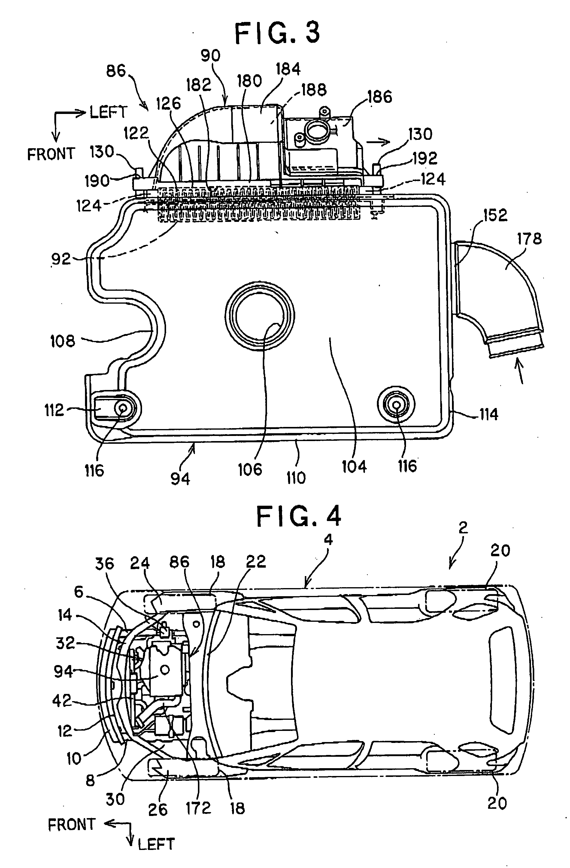
[0021]FIGS. 1-9 illustrate an embodiment of the present invention. FIGS. 4 and 5 show a vehicle 2, a vehicle body 4, a right side frame 6, a left side frame 8, a front bumper member 10, a front cross member 12, a front upper member 14, a front center member 16, front vehicle wheels 18, and rear vehicle wheels 20. The vehicle 2 includes an engine room 30 which is separated by a dash panel 22 extending widthwise of the vehicle body 4 and which is enclosed by a right fender 24, a left fender 26, and an engine hood 28 forward of the dash panel 22.

[0022] In the engine room 30, an engine 32 and a transmission 34 are arranged side-by-side transversely of the length of the vehicle 2. As shown in FIGS. 6-9, the engine 32 is inclined toward a front side and is supported by a right engine mount 36, a left engine mount, a front engine mount 38, and a rear engine mount 40. The engine 32 is mounted rightward of the engine room 30. The transmission 34 is connected to a joint surface F on a left s...


PUM


Abstract

The purpose of the intake system, which is disposed in a limited space above the engine, is to improve engine performance by preventing increase in both temperature and resistance of intake air, and also to reduce noise of the intake air. In the intake system, a rear wall extending downwardly is formed in a lower half body that is joined to a rear end of an engine cover, and a mounting frame section for attaching an element is formed in a rear wall section. An upstream-side casing is formed forward of the rear wall section. An intake duct has a downstream end connected to a front surface of the upstream-side casing adjacent to a transmission. Further, the intake duct extends widthwise of the vehicle and has an upstream end opened to the side edge of the engine cover adjacent to the transmission. A resonance chamber casing is joined to the side departing from the transmission through a communication pipe forward of the upstream-side casing. The resonance chamber casing is formed to extend along the full width of the engine cover so as to cover the front of the intake duct.

Description

FIELD OF THE INVENTION [0001] This invention relates to intake systems of an engine, and more particularly to an intake system of the engine which is disposed in a limited space above the engine, and improves the engine performance by preventing increase in both temperature and resistance of the intake air, and also reduces the noise of the intake air. BACKGROUND OF THE INVENTION [0002] The engine mounted in an engine room of the vehicle is equipped with the intake system for introducing the intake air to cylinders. In the intake system of the engine, an element of an air cleaner removes the dust in the intake air, a resonance chamber reduces the intake noise, and an intake manifold introduces the intake to the respective cylinders. [0003] There are some conventional intake systems of the engine which include an air cleaner that has an element disposed between upper and lower casings and that is integrated to an engine cover covering the top of the engine. Such conventional intake s...

Claims


Application Information

Patent Timeline
Patent Type & Authority Applications(United States)
IPC IPC(8): F02M35/10F02M35/02
CPCF02M35/024F02M35/04F02M35/1255F02M35/161F02M35/14
Inventor OHARA, MINAO
Owner SUZUKI MOTOR CORP
Why Eureka
Try Eureka