Rigid-flex wiring board and method for producing same

a rigid-flex wiring board and rigid-flex technology, applied in the direction of printed circuit aspects, non-metallic protective coating applications, lighting and heating apparatuses, etc., can solve the problems of delayed signal propagation, more serious delay in signal propagation, and unstable high-speed signal transmission, etc., to achieve stable signal transmission

Inactive Publication Date: 2007-01-18
IBIDEN CO LTD
View PDF12 Cites 100 Cited by
  • Summary
  • Abstract
  • Description
  • Claims
  • Application Information

AI Technical Summary

Benefits of technology

[0039] As having been described with the above flex-rigid wiring boards (2) to (4), the present invention provides a flex-rigid wiring board thinner than the conventional flex-rigid wiring board having a connecting structure advantageous for assuring a stable signal transmission.

Problems solved by technology

However, the wiring board in which a flexible substrate and rigid substrate are electrically connected to each other through a plated through-hole with the above-mentioned conventional wiring-board technology is not advantageous in that when it is used with a frequency of higher than 1 GHz, signal propagation is delayed and high-speed signal transmission is not stable.
Especially when the wiring board is used with a frequency of higher than 5 GHz, the signal propagation is more seriously delayed and instability of the high-speed signal transmission is greater.
Also, the wiring board produced with the conventional wiring-board technology was found, as a result of the reliability test made in the cooling / heating cycle test, to have the electrical connection thereof deteriorated.
Further, since the conventional flex-rigid wiring board is formed either by fixing a flexible substrate to an outermost rigid substrate with an anisotropic adhesive or by laying a flexible substrate between both outermost rigid substrates, so it cannot be designed thinner.

Method used


Image

  • Rigid-flex wiring board and method for producing same
  • Rigid-flex wiring board and method for producing same
  • Rigid-flex wiring board and method for producing same

Examples


example 1

[0121] (A) Preparing a Flexible Substrate

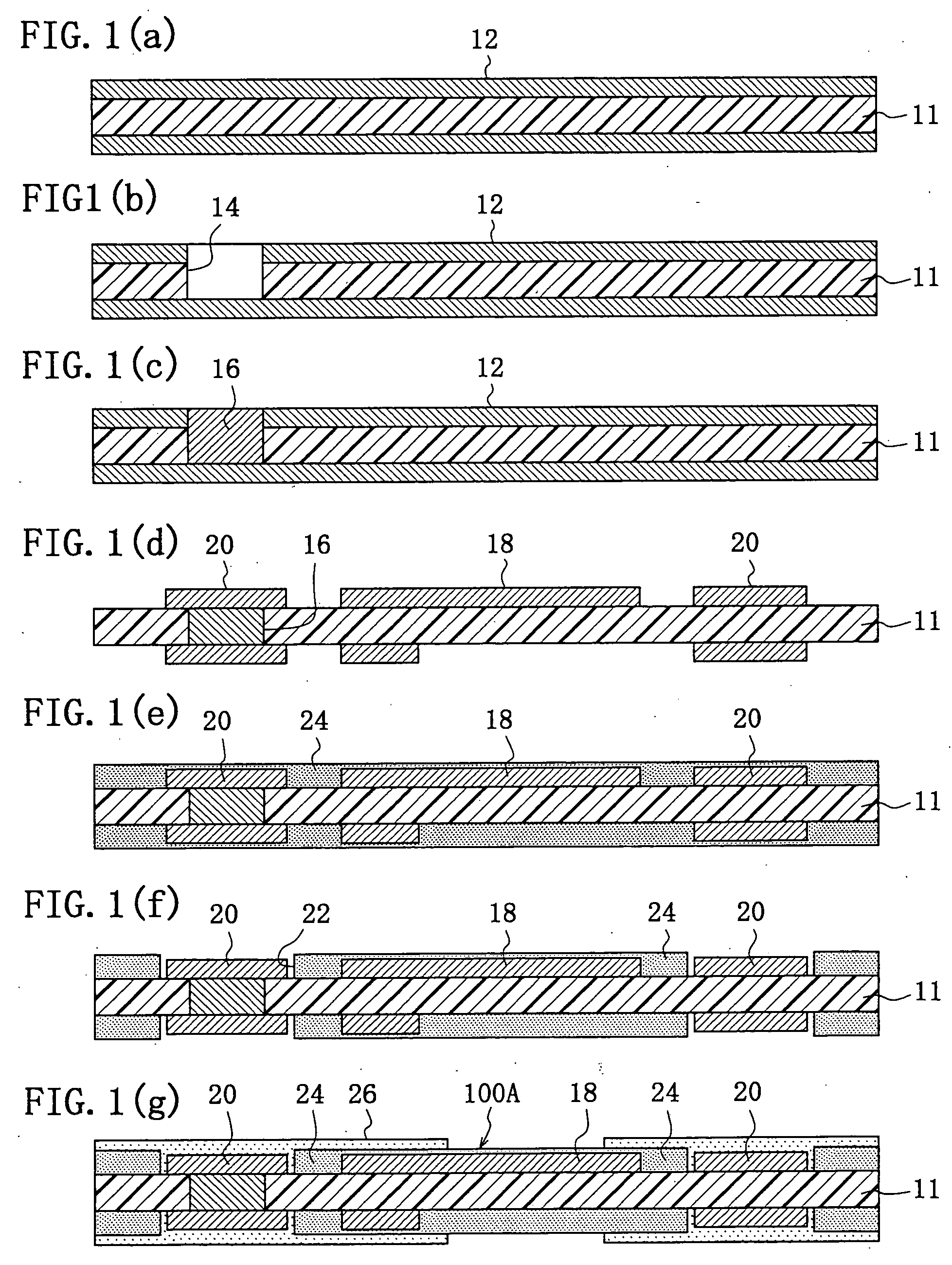
[0122] (1) For producing the flex-rigid wiring board as the example 1 of the present invention, a laminated film (ESPANEX SB by Shin-Nittetsu Chemicals) formed from a 25 μm-thick insulative film 11 of polyimide resin having a 30 μm-thick copper foil 12 laminated on either side thereof (as in FIG. 1(a)) is used as a base material for preparation of a flexible substrate 100A included in the flex-rigid wiring board.

[0123] (2) A resist layer is formed on the copper foil on the laminated film, and exposed to light and developed to form a circular opening of 300 μm in diameter. The copper foil was etched using a cupric chloride aqueous-solution to form the opening in the copper foil. Carbon-dioxide laser or the like is irradiated to the opening to form an opening 14 that penetrates the resin layer to the copper foil on the back of the insulative film (as in FIG. 1(b)).

[0124] (3) The opening 14 formed in the step (2) above is fully filled with co...

example 2

[0154] A flex-rigid wiring board is produced similarly to the aforementioned example 1 except that each coverlay 24 formed on the flexible substrate 100A is formed to a thickness of 25 μm.

example 3

[0155] A flex-rigid wiring board is produced similarly to the example 1 except that each coverlay 24 formed on the flexible substrate 100A is formed to a thickness of 40 μm.


PUM

PropertyMeasurementUnit
frequencyaaaaaaaaaa
frequencyaaaaaaaaaa
thicknessaaaaaaaaaa

Abstract

In a flex-rigid wiring board in which a rigid substrate formed from a rigid base material and a flexible substrate formed from a flexible base material are stack-joined and electrically connected to each other, the flexible substrate including a conductive layer having interconnecting electrode pads provided on at least one surface thereof, and the rigid substrate including a conductive layer having interconnecting electrode pads provided on at least one surface thereof in a position opposite to the interconnecting electrode pads on the rigid substrate, are locally connected electrically to each other with an anisotropic conductive adhesive layer interposed between conductive layers of substrate portions each including at least the interconnecting electrode pads. In this flex-rigid wiring board, transmission of high-frequency signals can be prevented from being delayed, noises can be suppressed, and an excellent electrical connection and connection reliability be assured.

Description

FIELD OF THE INVENTION [0001] The present invention generally relates to a wiring board including a flexible substrate and rigid substrate, and more particularly to a wiring board characterized in the connection between a flexible substrate and rigid substrate stack-joined to each other in a rigid portion, among others, of the wiring board. BACKGROUND ART [0002] The recent portable electronic devices such as a foldable mobile phone and the like use a flex-rigid wiring board. Normally in such a wiring board, rigid or non-flexible portions and a flexible portion are joined to each other with a flexible substrate laid between them, and wiring pattern layers on the surfaces of the flexible and rigid substrates stacked together are electrically connected to each other via a plated through-hole conductive layer in the rigid portion as shown in FIG. 12 (as disclosed in the Japanese Patent Application Laid Open No. 90756 of 1993, for example). [0003] Also, there has been proposed a flex-rig...

Claims


Application Information

Patent Timeline
Patent Type & Authority Applications(United States)
IPC IPC(8): H05K1/03H05K1/14H05K3/00H05K3/28H05K3/32H05K3/36H05K3/46
CPCH05K1/117H05K3/244H05K3/323H05K3/361H05K3/4614H05K3/462Y10T29/49126H05K2201/09063H05K2201/09481H05K2201/096H05K2201/09781H05K2201/09845H05K2203/063H05K3/4691H05K1/14H05K3/36
Inventor KAWAGUCHI, KATSUOFUTAMURA, HIROFUMIMIKADO, YUKINOBUITO, SOTARU
Owner IBIDEN CO LTD
Why Eureka
Try Eureka