Fuel injection valve

a fuel injection valve and fuel technology, applied in the direction of fuel injection apparatus, spraying apparatus, charge feed system, etc., can solve the problems of limited opportunities for intervening in the formation of mixture cloud, limited possibilities for lowering fuel consumption and exhaust emissions, etc., and achieve the effect of shortened service li

Inactive Publication Date: 2007-01-18
ROBERT BOSCH GMBH
View PDF5 Cites 22 Cited by
  • Summary
  • Abstract
  • Description
  • Claims
  • Application Information

AI Technical Summary

Benefits of technology

[0009] It is advantageous that none of the spray-discharge orifices is directed toward the spark plug so that coking of the spark gap and a shortened service life are able to be avoided.

Problems solved by technology

Particularly disadvantageous in the fuel injector of the aforementioned are the limited opportunities for intervening in the formation of the mixture cloud.
Accordingly, the possibilities for lowering the fuel consumption and exhaust emissions are limited.

Method used


Image

  • Fuel injection valve
  • Fuel injection valve
  • Fuel injection valve

Examples


Embodiment Construction

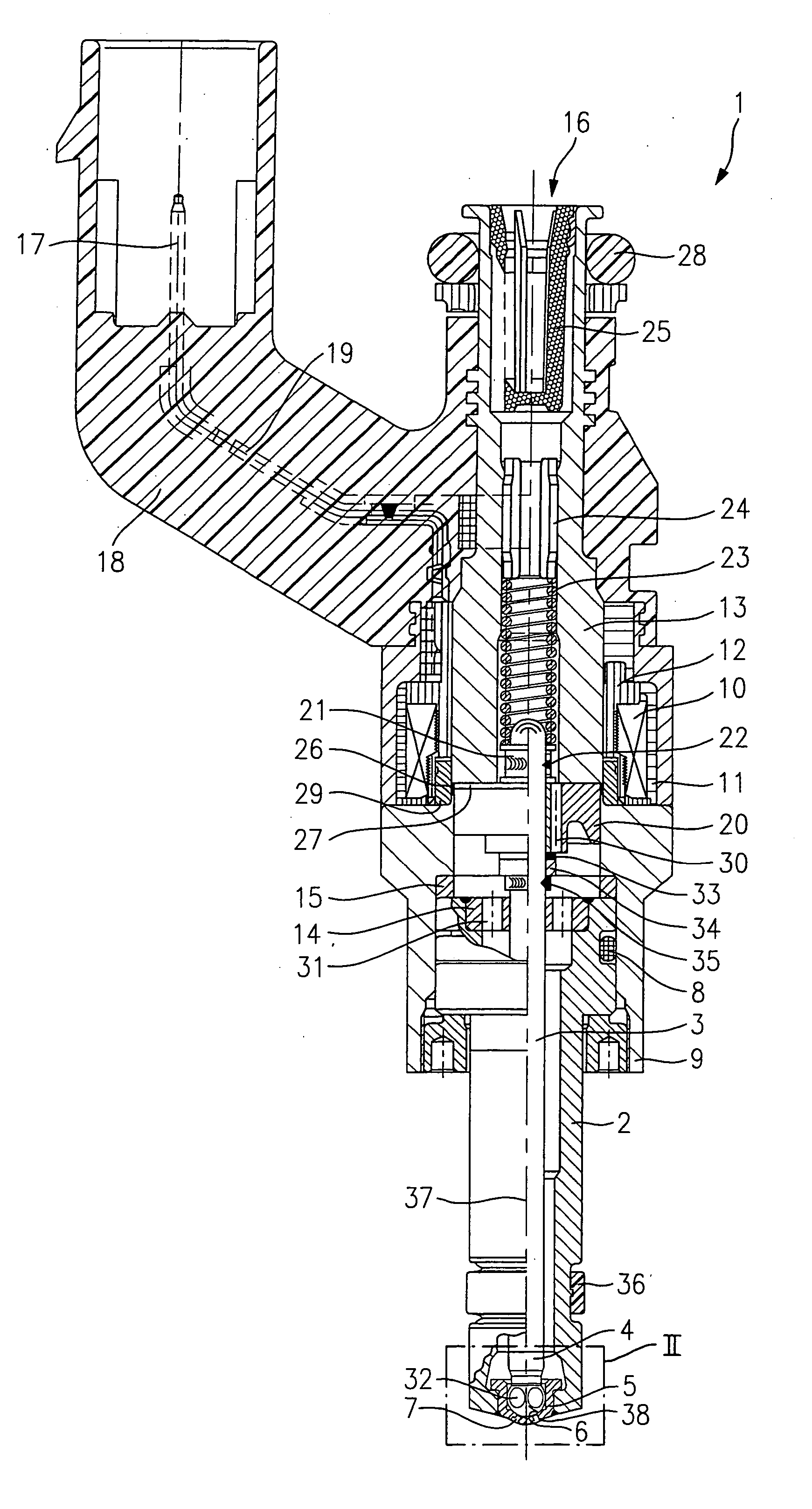
[0013]FIG. 1 shows a sectional view of an exemplary embodiment of a fuel injector 1 according to the present invention. It is in the form of a fuel injector for fuel-injection systems of mixture-compressing internal combustion engines having external ignition. Fuel injector 1 is suited for the direct injection of fuel into a combustion chamber (not shown further) of an internal combustion engine.

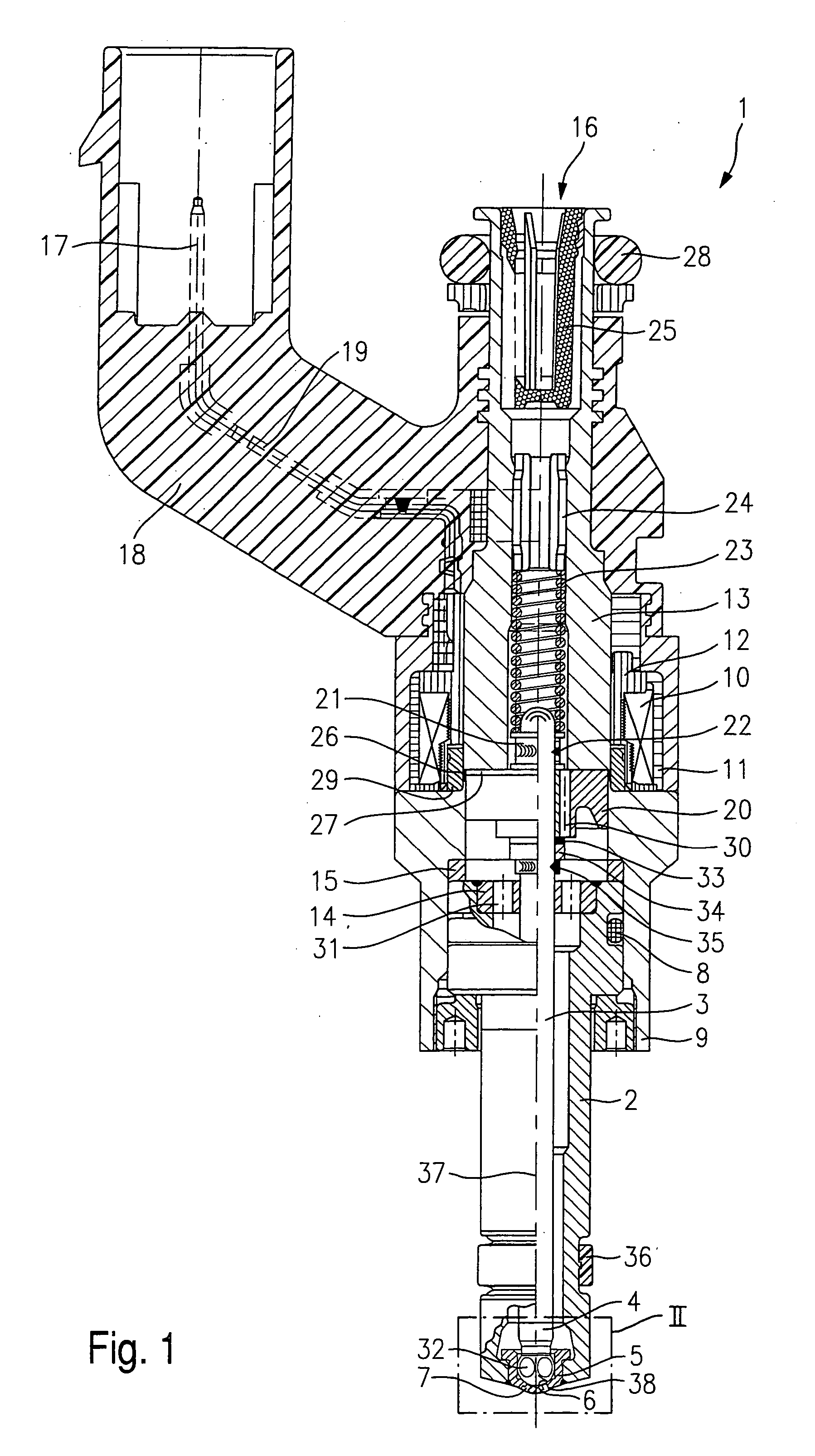
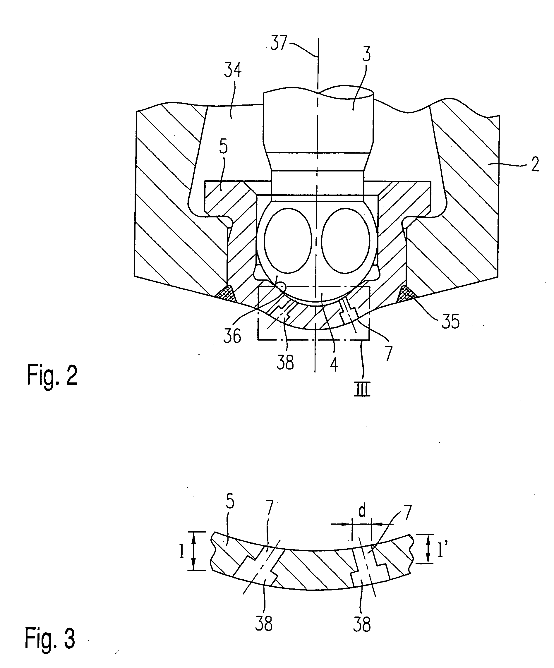
[0014] Fuel injector 1 is composed of a nozzle body 2 in which a valve needle 3 is positioned. Valve needle 3 is in operative connection with a valve-closure member 4, which cooperates with a valve-seat surface 6 located on a valve-seat member 5 to form a sealing seat. The valve-closure body has a substantially spherical shape, and in this way contributes to an offset-free guidance in valve-seat body 5. In the exemplary embodiment, fuel injector 1 is an inwardly opening fuel injector, which has two spray-discharge orifices 7. According to the present invention, spray-discharge orifices 7 ar...


PUM


Abstract

A fuel injector for the direct injection of fuel into a combustion chamber of an internal combustion engine includes an energizable actuator, a valve needle, which is in operative connection with the actuator and acted upon by a restoring spring in a closing direction to actuate a valve-closure member, which forms a sealing seat together with a valve-seat surface formed at a valve-seat body. The valve-seat body includes at least two spray-discharge orifices. The pressure of the fuel flowing through the fuel injector is greater than 10 bar.

Description

FIELD OF THE INVENTION [0001] The present invention is directed to a fuel injector for the direct injection of fuel into an internal combustion engine. BACKGROUND INFORMATION [0002] Published German patent document DE 196 25 059 discloses a fuel injector for the direct injection of fuel into a mixture-compressing internal combustion engine having external ignition, which injector provides a flow path for the fuel from a fuel intake to a spray-discharge orifice, in which flow path a plurality of fuel channels are arranged in front of the discharge orifice, the cross-section of the fuel channels determining the amount of fuel injected per time unit at the given fuel pressure. In order to influence the fuel distribution in an injected mixture cloud and to achieve selective skeining of the mixture cloud, at least a portion of the fuel channels is aligned such that in an open fuel injector the fuel jets exiting from the fuel channels are injected directly through the spray-discharge orif...

Claims


Application Information

Patent Timeline
Patent Type & Authority Applications(United States)
IPC IPC(8): F02M61/00F02M51/06F02M61/18
CPCF02M51/0671F02M51/0675F02M61/1853F02M61/1846F02M61/1833
Inventor MAIER, MARTINHEYSE, JOERG
Owner ROBERT BOSCH GMBH
Why Eureka
Try Eureka