Methods and apparatus for dividing a clock signal

a clock signal and clock frequency technology, applied in the field of integrated circuits, can solve the problems of increasing computing power and complexity, single clock frequency is often not enough to accommodate every device, and the frequency range of most conventional clock dividers is not suitable for dividing clock signals in this frequency rang

Active Publication Date: 2007-01-18
MICRON TECH INC
View PDF35 Cites 5 Cited by
  • Summary
  • Abstract
  • Description
  • Claims
  • Application Information

AI Technical Summary

Benefits of technology

[0011] There is provided a true single phase logic clock divider that is configured to divide a clock signal by increments of two, three, four, or six. Because the true single phase logic clock divider is based on true single phase logic instead of static logic, the true single phase logic clock divider is able to reliably divide clock signals that could not reliably be divided by clock dividers based on static logic gates. There is also provided a method comprising receiving an input signal with a frequency between 2.5 gigahertz and 4 gigahertz and producing an output signal with a frequency approximately one-third of the frequency of the input signal.

Problems solved by technology

For a variety of reasons, however, a single clock frequency is often not sufficient to accommodate every device or circuit in a complex computer or other electronic device.
As most people are aware, computers and computer-related technologies have been steadily increasing in computing power and complexity over the past several years.
Most conventional clock dividers, however, are not suitable for dividing clock signals in this frequency range, because most conventional clock dividers employ static logic gates and flip-flops that have internal logic gate delays and set-up times that are slower than the period (i.e., 1 / frequency) of clock signals above two gigahertz.
In other words, conventional, static-logic-based clock dividers are often too slow to accurately divide clock signals with frequencies above two gigahertz.

Method used


Image

  • Methods and apparatus for dividing a clock signal
  • Methods and apparatus for dividing a clock signal
  • Methods and apparatus for dividing a clock signal

Examples


Embodiment Construction

[0017] One or more specific embodiments of the present invention will be described below. In an effort to provide a concise description of these embodiments, not all features of an actual implementation are described in the specification. It should be appreciated that in the development of any such actual implementation, as in any engineering or design project, numerous implementation-specific decisions must be made to achieve the developers' specific goals, such as compliance with system-related and business-related constraints, which may vary from one implementation to another. Moreover, it should be appreciated that such a development effort might be complex and time consuming, but would nevertheless be a routine undertaking of design, fabrication, and manufacture for those of ordinary skill having the benefit of this disclosure.

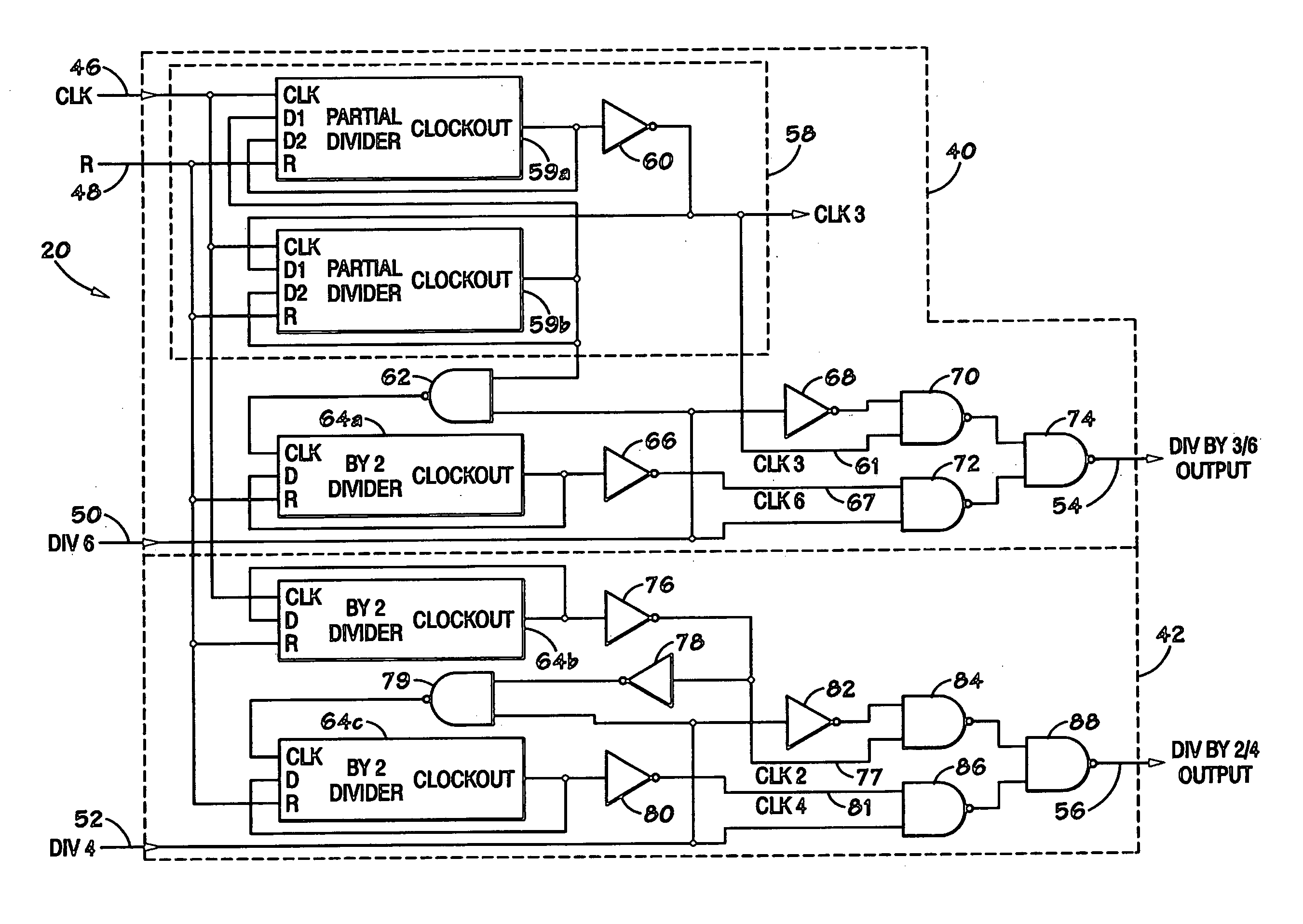
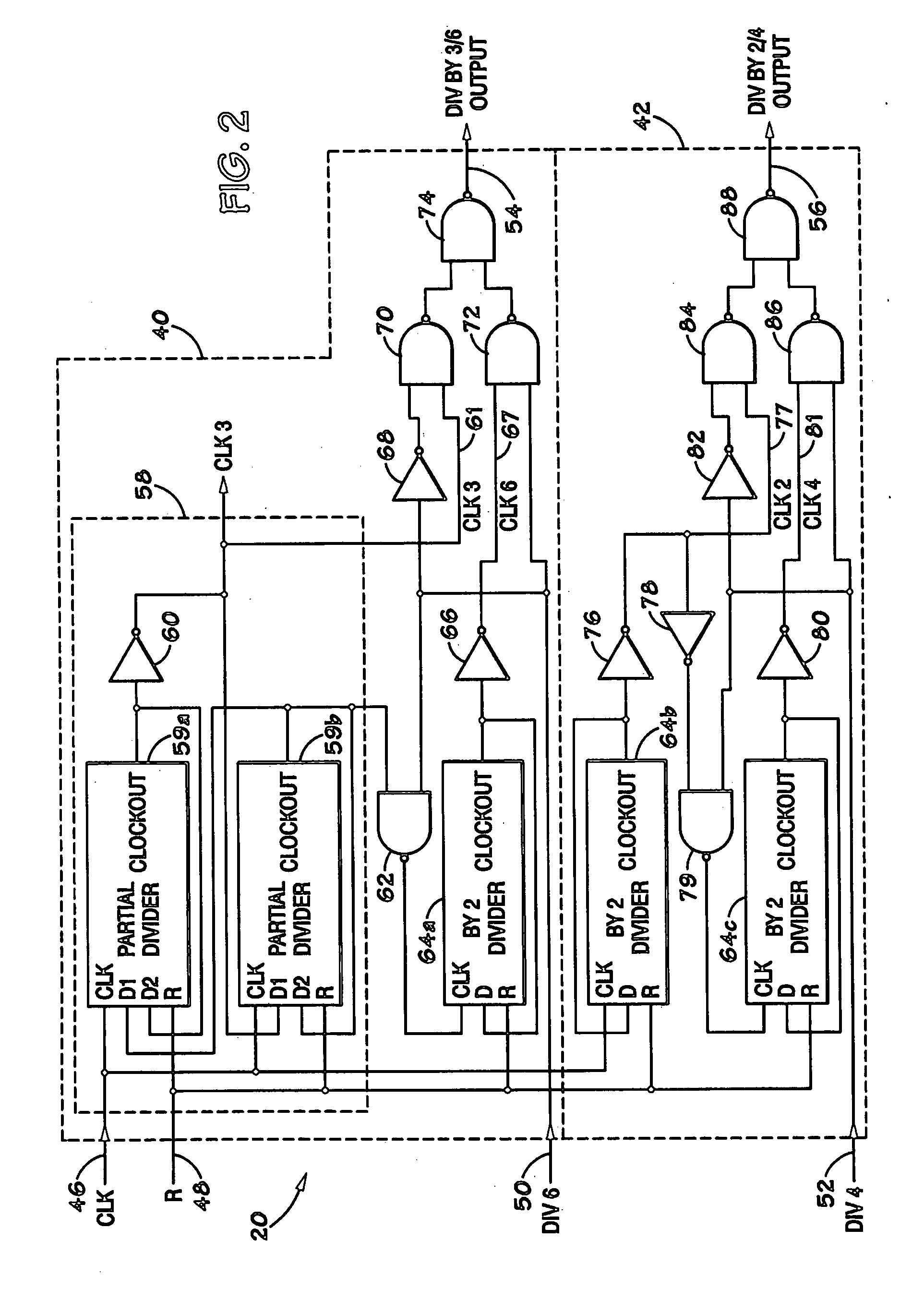
[0018] As described above, conventional clock dividers employ static logic gates and flip-flops to divide the frequency of a clock signal. Static logic ...


PUM


Abstract

There is provided a true single phase logic clock divider that is configured to divide a clock signal by increments of two, three, four, or six. Because the true single phase logic clock divider is based on true single phase logic instead of static logic, the true single phase logic clock divider is able to reliably divide clock signals that could not reliably be divided by clock dividers based on static logic gates. There is also provided a method comprising receiving an input signal with a frequency between 2.5 gigahertz and 4 gigahertz and producing an output signal with a frequency approximately one-third of the frequency of the input signal.

Description

CROSS-REFERENCE TO RELATED APPLICATIONS [0001] The following commonly owned applications and patents are hereby incorporated by reference for all purposes: [0002] U.S. patent application Ser. No. ______, filed concurrently herewith, entitled “Efficient Clocking Scheme For Ultra High-Speed Systems,” By Feng Lin.BACKGROUND OF THE INVENTION [0003] 1. Field of the Invention [0004] The present invention relates generally to integrated circuits and, more particularly, to a clock divider employing true single phase logic. [0005] 2. Description of the Related Art [0006] This section is intended to introduce the reader to various aspects of art that may be related to various aspects of the present invention, which are described and / or claimed below. This discussion is believed to be helpful in providing the reader with background information to facilitate a better understanding of the various aspects of the present invention. Accordingly, it should be understood that these statements are to ...

Claims


Application Information

Patent Timeline
Patent Type & Authority Applications(United States)
IPC IPC(8): H03K23/00
CPCH03K23/60H03K23/44G06F1/04G06F1/06H03K23/00
Inventor LIN, FENG
Owner MICRON TECH INC
Why Eureka
Try Eureka