Engine control device of work vehicle

Active Publication Date: 2007-01-18
KOMATSU LTD
View PDF14 Cites 34 Cited by
  • Summary
  • Abstract
  • Description
  • Claims
  • Application Information

AI Technical Summary

Benefits of technology

[0067] According to the fifth and sixth aspects of the invention, for example as shown in FIG. 12, the low-horsepower power curve R3′ is set as a power curve having high torque rise by drawing a curved line on which a same or substantially same high torque as on the maximum-horsepower power curve R1 is obtained in the low speed range of the engine 1, drawing a curved line

Problems solved by technology

Additionally, since the cooling fan is large in size, the

Method used


Image

  • Engine control device of work vehicle
  • Engine control device of work vehicle
  • Engine control device of work vehicle

Examples


first embodiment

[0081] An engine control apparatus for use in a work vehicle according to a preferred embodiment of the present invention will be described with reference to the accompanying drawings.

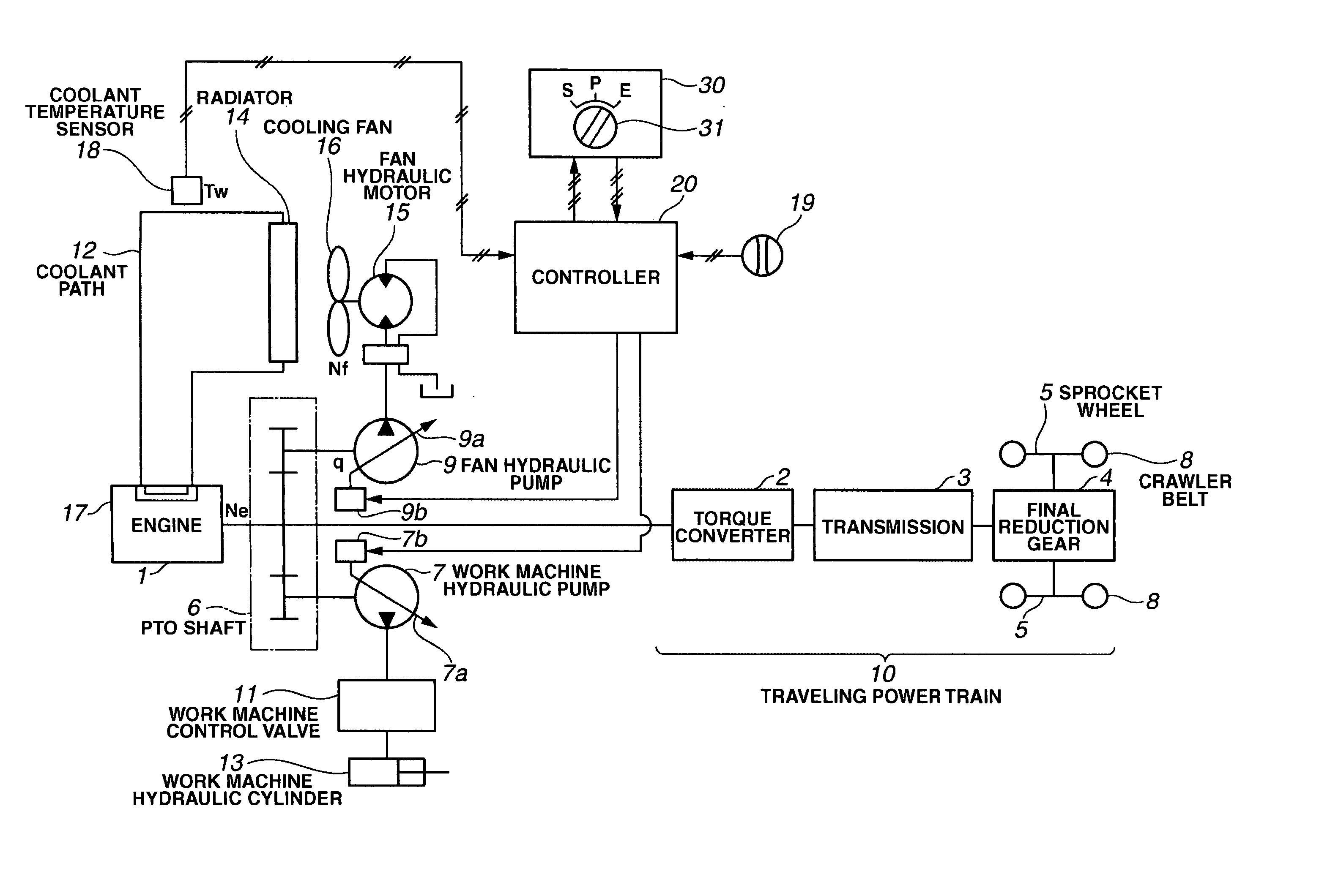
[0082]FIG. 3 shows a part of a bulldozer according to an embodiment of the present invention, the part relating to the present invention.

[0083] As shown in FIG. 3, the bulldozer has an engine 1 whose output shaft is connected to a power take-off (PTO) shaft 6. The PTO shaft 6 is connected to a torque converter 2, and also connected to a work machine hydraulic pump 7 and a fan hydraulic pump 9.

[0084] The work machine hydraulic pump 7 and the fan hydraulic pump 9 are variable displacement hydraulic pumps having swash plate drive units 7b and 9b, respectively. The swash plate drive units 7b and 9b vary the inclination angles of swash plates 7a and 9a, respectively, to change the pump capacity q (cc / rev).

[0085] The output of the engine 1 is transmitted to a sprocket wheel 5 through the torque converter...

second embodiment

[0162] In the first embodiment described above, the drive of the cooling fan 16 is controlled, as shown in FIG. 6B, so as to increase the fan speed Nf according to the increase of the coolant temperature Tw, while no consideration is given to the magnitude of the engine speed.

[0163] A second embodiment of the present invention will be described in which the drive of the cooling fan 16 is controlled in consideration of the magnitude of the engine speed.

[0164]FIG. 10A is a diagram schematically showing a comparative example to this second embodiment, illustrating relationship between speed Ne of the engine 1 and fan speed Nf of the cooling fan 16. As shown in FIG. 10A, the speed Nf of the cooling fan 16 increases in proportion to the increase of the speed Ne of the engine 1. This means that, in the low speed range where the engine speed Ne is lower than a predetermined speed Nec, the fan speed Nf decreases in proportion to the decrease of the engine speed Ne, while the fan horsepowe...

third embodiment

[0188] The foregoing description of the second embodiment has been made on the assumption that the work vehicle is provided with the work mode selection switch 31. However, the second embodiment above may be modified as required to be applicable to a work vehicle having no work mode selection switch 31.

[0189] For example, the present invention may be embodied, as shown in FIG. 13C, such that the power curve R1 is selected when the detected coolant temperature is in the high temperature range A, the power curve R2 is selected when the detected coolant temperature is in the medium temperature range B, and the power curve R3′ is selected when the detected coolant temperature is in the low temperature range C, in the same manner as when the power mode P is selected in FIG. 13A, and the engine 1 is controlled so that a selected power curved is obtained.

[0190] The present invention is not limited to application in a bulldozer, but is also applicable to any desired work vehicle, as long ...


PUM


Abstract

An engine control apparatus for a work vehicle having a cooling fan or an auxiliary device driven by an engine. The engine control apparatus is capable of operating the work vehicle with the importance placed either on amount of work or fuel economy depending on the situation, and preventing the input of excessive traveling horsepower (or working horsepower), regardless of a selected work mode, to ensure durability of the traveling power train (or work machine drive equipment). Upon selection of a work mode by the work mode selection switch, a controller controls the engine to obtain a power curve selected from those selectable for the selected work mode can be obtained, based on the coolant temperature range and the selected work mode, so that the input torque transmitted to the traveling power train does not surpass the upper limit for the input torque (rated output).

Description

BACKGROUND OF THE INVENTION [0001] 1. Technical Field [0002] The present invention relates to an engine control apparatus for use in a work vehicle. [0003] 2. Related Art [0004] When the work vehicle is a bulldozer, engine output (torque) is distributed to traveling load, work machine load, and cooling fan load through a PTO shaft. This means that the engine output (torque) is transmitted to a sprocket wheel through a traveling power train (power transmission) such as a torque converter and a transmission (hydraulic clutch), whereby crawler belts are driven and the vehicle is caused to travel. Thus, a portion of the engine horsepower is consumed as traveling horsepower (horsepower absorbed by the torque converter). The traveling horsepower input to the traveling power train must be suppressed to a certain horsepower level or lower in consideration of durability of the traveling power train. [0005] The engine output is also transmitted to a work machine hydraulic pump to drive the wo...

Claims


Application Information

Patent Timeline
IPC IPC(8): G06F19/00G06G7/70
CPCE02F9/2246F02D11/105F02D2250/26F02D2200/604F02D2250/18F02D41/1497
Inventor KAMADO, MITSUHIKOYAMAMOTO, SHIGERU
Owner KOMATSU LTD
Why Eureka
Try Eureka