Catalyst diagnosis apparatus for internal combustion engine

Inactive Publication Date: 2007-01-25
HITACHI LTD
View PDF13 Cites 18 Cited by
  • Summary
  • Abstract
  • Description
  • Claims
  • Application Information

AI Technical Summary

Benefits of technology

[0027] With the catalyst diagnosis apparatus the for internal combustion engine according to the present invention, since the degradation of the three-way catalyst is determined in combination of the reaction rate calculated by the reaction rate calculation unit and the OSC indicator calculated by the OSC indica

Problems solved by technology

When the degradation determination method using the catalyst temperature is actually performed like the catalyst degradation detection device disclosed in Patent Document 1, the following problem may occur.
It is hence difficult to precisely detect the catalyst temperature.
Even in the case of using a temperature sensor, it is also difficult to precisely detect the

Method used


Image

  • Catalyst diagnosis apparatus for internal combustion engine
  • Catalyst diagnosis apparatus for internal combustion engine
  • Catalyst diagnosis apparatus for internal combustion engine

Examples


first embodiment

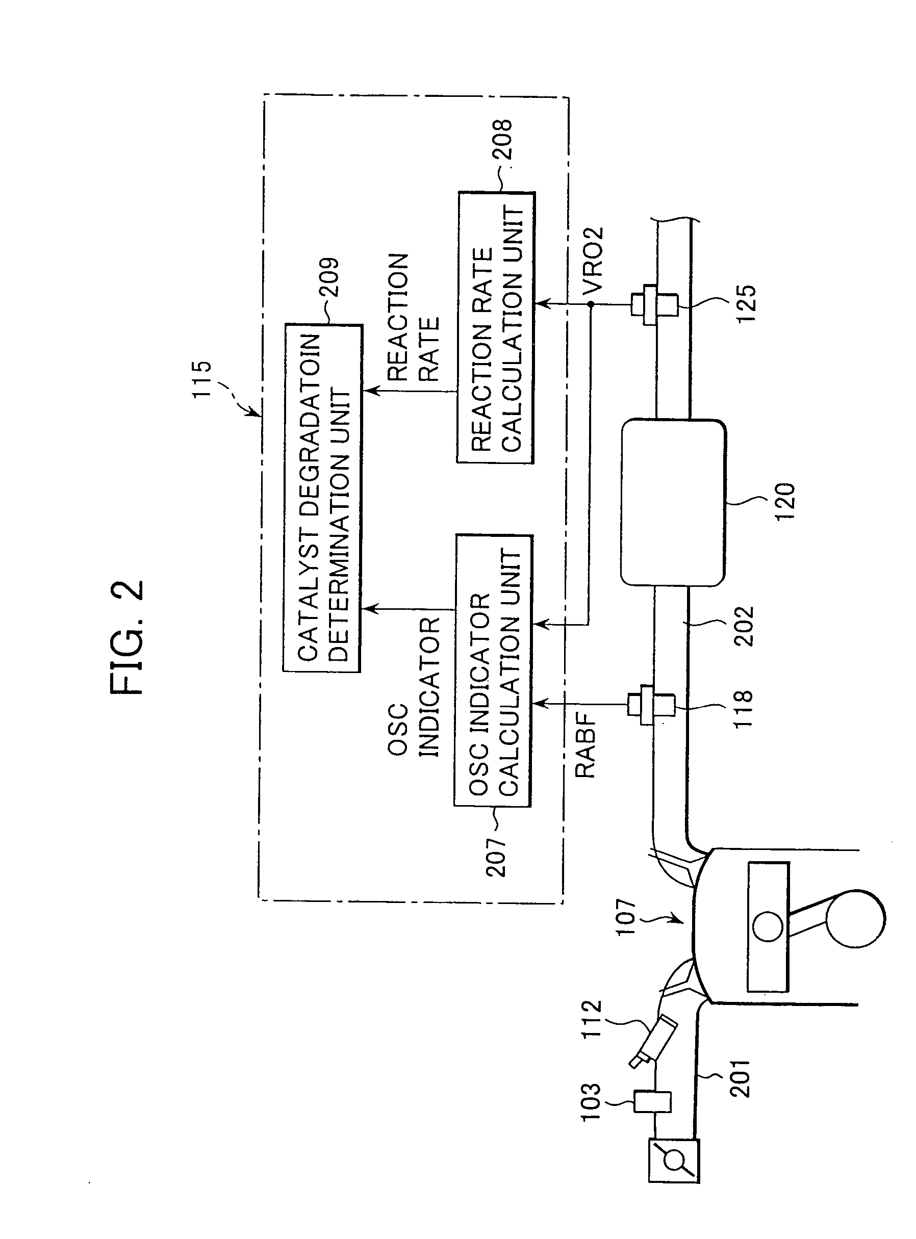
[0063] With reference to FIG. 2, the following description is made of a catalyst diagnosis apparatus according to the present invention and an outline of an internal combustion engine to which is applied the catalyst diagnosis apparatus.

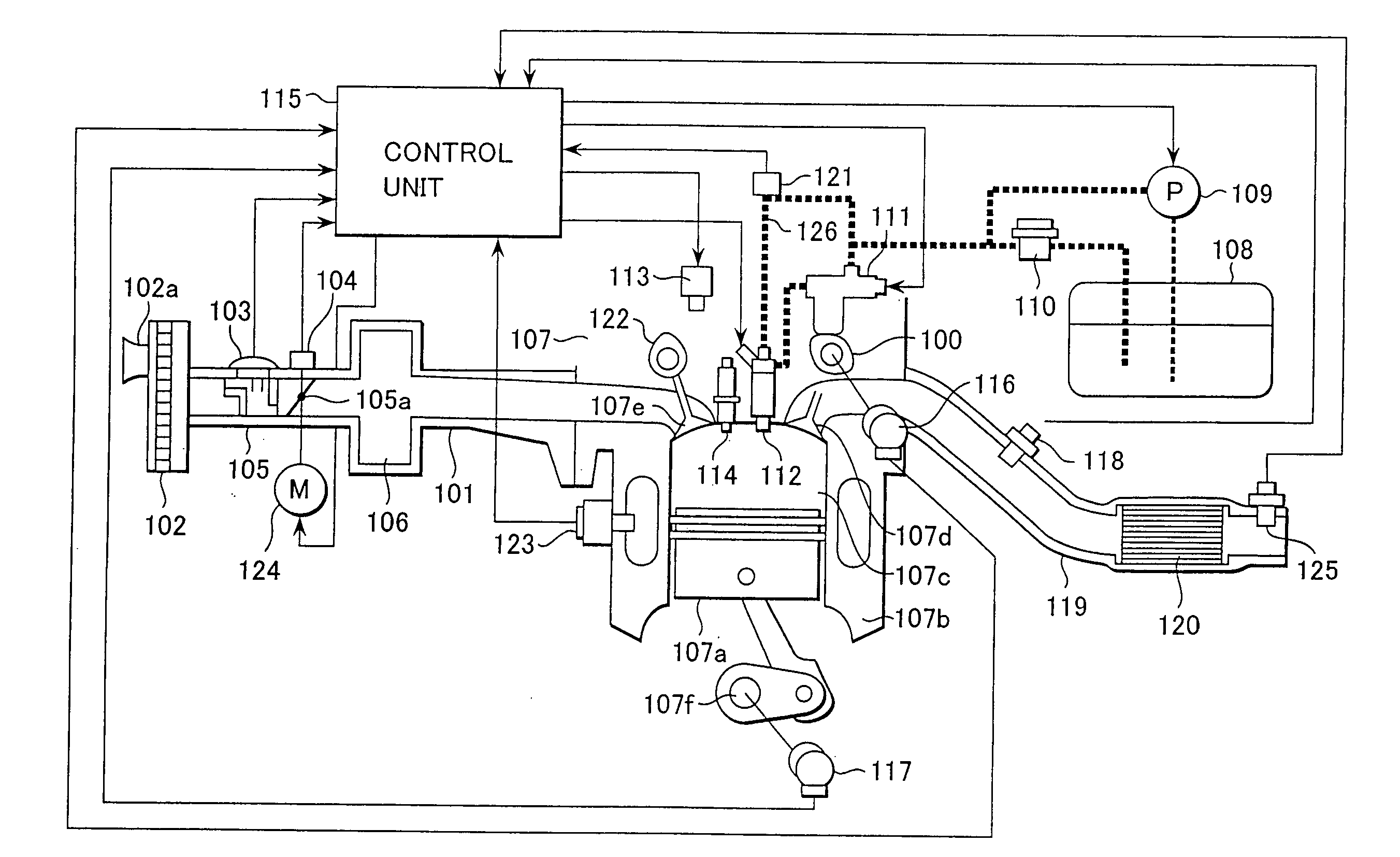
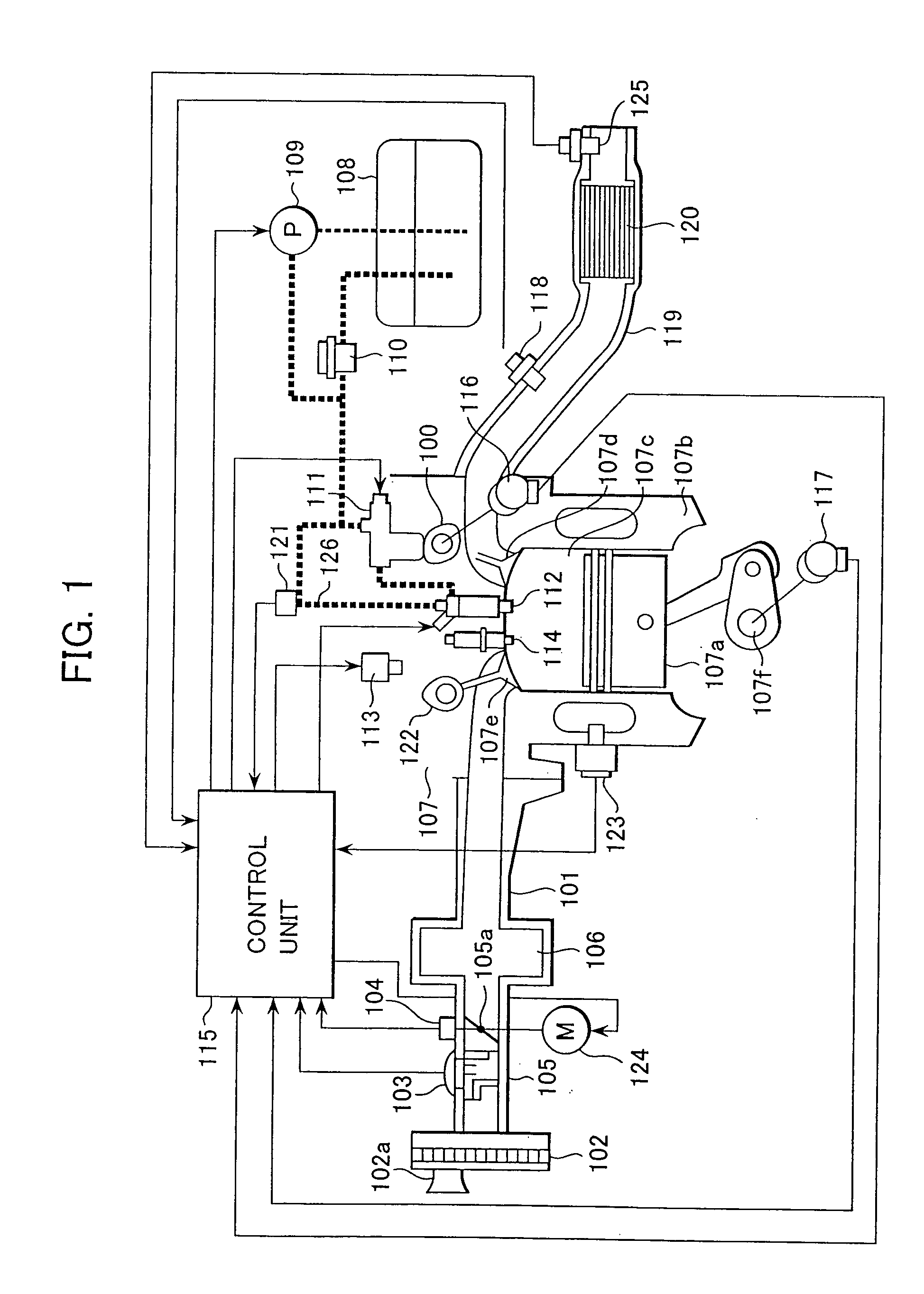
[0064] In an intake passage 201 of the internal combustion engine 107, the airflow sensor 103 is disposed as an intake air mass detection unit for detecting the intake air mass.

[0065] The three-way catalyst 120 is disposed midway an exhaust passage 202 of the internal combustion engine 107. Looking at the exhaust passage 202 in the direction of flow of exhaust gas therein, the linear air-fuel ratio sensor 118 for detecting the air-fuel ratio in the exhaust gas is disposed upstream of the three-way catalyst 120, and the oxygen sensor 125 for detecting the oxygen density in the exhaust gas is disposed downstream of the three-way catalyst 120.

[0066] The control unit 115 is constituted by a microcomputer and executes computer programs in accordance wit...

second embodiment

[0097] With reference to FIG. 11, the following description is made of a catalyst diagnosis apparatus according to the present invention and an outline of an internal combustion engine to which is applied the catalyst diagnosis apparatus. Note that components in FIG. 11 corresponding to those in FIG. 2 are denoted by the same reference numerals and a description thereof is omitted here.

[0098] In this embodiment, the control unit 115 executes computer programs in accordance with software to implement the functions of a center air-fuel ratio calculation unit 1108, a center air-fuel ratio determination unit 1109, an air-fuel ratio control unit 1110, an OSC indicator calculation unit 1111, a reaction rate calculation unit 1112, and a catalyst degradation determination unit 209, thereby realizing the catalyst diagnosis apparatus.

[0099] In this embodiment, because the center air-fuel ratio calculation unit 1108, the center air-fuel ratio determination unit 1109, and the air-fuel ratio co...

third embodiment

[0140] With reference to FIG. 18, the following description is made of a catalyst diagnosis apparatus according to the present invention and an outline of an internal combustion engine to which is applied the catalyst diagnosis apparatus. Note that components in FIG. 18 corresponding to those in FIG. 2 are denoted by the same reference numerals and a description thereof is omitted here.

[0141] In this third embodiment, a reaction rate revision unit 1809 for revising the reaction rate based on the output of the airflow sensor 103 is added to the arrangement in first embodiment.

[0142] A reaction rate calculation unit 1807 calculates the reaction rate in the three-way catalyst 120 based on the output VRO2 of the oxygen sensor 125, and then revises the calculated reaction rate in accordance with a reaction rate revision amount calculated by the reaction rate revision unit 1809.

[0143] With such a process, even when the reaction rate is changed during a period from the calculation of the...


PUM


Abstract

A catalyst diagnosis apparatus comprises a reaction rate calculation unit for calculating a reaction rate of chemical reaction in a three-way catalyst based on an output of an oxygen sensor, and an OSC indicator calculation unit for calculating an OSC indicator indicating an oxygen storage capacity (OSC) of the three-way catalyst based on outputs of a linear air-fuel ratio sensor and the oxygen sensor, and a catalyst degradation determination unit for determining degradation of the three-way catalyst based on the reaction rate and the OSC indicator. The determination of the catalyst degradation can be performed with high accuracy in a manner adapted for influences of external environments, etc.

Description

BACKGROUND OF THE INVENTION [0001] 1. Field of the Invention [0002] The present invention relates to a catalyst diagnosis apparatus for internal combustion engine. More particularly, the present invention relates to a catalyst diagnosis apparatus for an internal combustion engine, which diagnoses whether a three-way catalyst disposed in an exhaust passage of the internal combustion engine is degraded, and also relates to an automobile equipped with an internal combustion engine including the catalyst diagnosis apparatus. [0003] 2. Description of the Related Art [0004] A three-way catalyst has hitherto been disposed midway an exhaust passage to purify and clean not-yet-burnt hydro carbons (HC), carbon monoxide (CO), and nitrogen oxides (NOx), i.e., harmful components in exhaust gas exhausted from an internal combustion engine. [0005] In such an exhaust cleaning device, if the three-way catalyst is degraded or failed for some reason, the efficiency of cleaning the harmful components i...

Claims


Application Information

Patent Timeline
IPC IPC(8): F01N3/00F01N7/00F01N3/20
CPCF01N11/007F01N2550/02Y02T10/22F02D2200/0814Y02T10/47F02D41/0295Y02A50/20Y02T10/12Y02T10/40
Inventor YAMAUCHI, SHINIIHOSHI, YOICHIHORI, TOSHIOKURASHIMA, YOSHIKUNI
Owner HITACHI LTD
Why Eureka
Try Eureka